Safety device of an elevator and safety control method

A safety device and safety control technology, which is applied in the field of elevator safety control and elevator safety device, can solve the problems that passengers are not easy to find and cannot remove obstacles quickly, and achieve the effect of reducing strength, reducing strength and reducing cost.

Inactive Publication Date: 2010-11-24
HITACHI LTD
9 Cites 13 Cited by

AI-Extracted Technical Summary

Problems solved by technology

In the meantime, although the situation that the elevator door cannot be closed due to the presence of foreign objects in the elevator car will be used to remind passengers through voice prom...

Method used

As shown in Figure 15, foreign object detection control unit 12 is after receiving the instruction (20) that the foreign object detection that sends out from elevator door control device 5 starts (20), opens light-emitting device 7a, 7b and light-emitting device 8 (S21), from The camera 10 acquires an image (S22), and turns off the light emitting devices 7a, 7b and the light emitting device 8 (S23). If the illuminated area is extracted according to the difference between the image when the light emitting device is not turned on and the image when the light emitting device is turned on, an image is also acquired in S21 before the light emitting device is turned on. Then, the image processing unit 11 performs the image processing described above with reference to FIGS. 5 and 6 and FIGS. The result is sent to the elevator door control device 5 (S25). In addition, the light-emitting devices 7a, 7b and the light-emitting device 8 may also be set to be turned on all the time, but they are set to be turned on only when an image is captured, so that power can be saved. In addition, by setting the ligh...

Abstract

The invention provides a safety device of an elevator, capable of detecting a rope-shaped foreign matter and a belt-shaped foreign matter with little diameter and reducing the repair and maintenance operation intensity and making the passenger quickly clear the foreign matter without effecting the appearance shape and when detecting the foreign matter. The safety device. The safety device of the elevator comprises lighting devices (8) arranged between an elevator door (1) at the elevator car side and its door sill (2) and between an elevator door (1) at the hall side and its door sill and capable of linearly lighting on the whole front-surface width of the elevator access door, a camera (10) arranged on the upper part of the elevator access door and an image processing unit (11) for processing the image obtained by the camera, in the safety device, the lighting device lights and the camera obtains the image on the door sill surface and the front end surface of the elevator door and the image processing unit extracts the area lighted by the lighting device and the presence of the foreign matter is detected based on whether the lighted area is separated or not.

Application Domain

Technology Topic

Image

  • Safety device of an elevator and safety control method
  • Safety device of an elevator and safety control method
  • Safety device of an elevator and safety control method

Examples

  • Experimental program(2)

Example

[0055] First embodiment
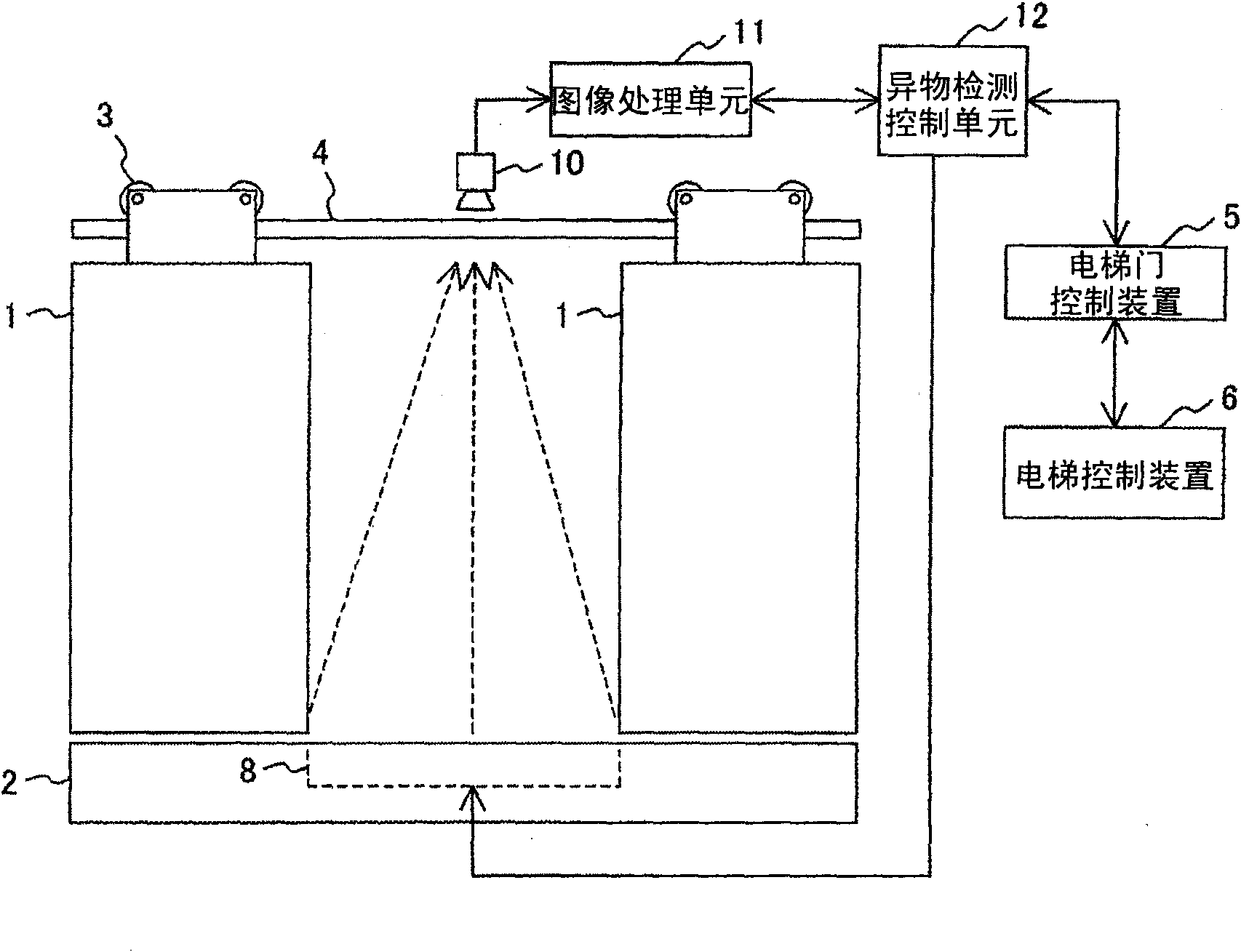
[0056] figure 1 It is a schematic diagram showing the structure of the elevator safety device according to the first embodiment of the present invention.
[0057] Such as figure 1 As shown, the center-divided elevator door adopting the safety device of this embodiment has an elevator door 1, a threshold that guides the lower part of the elevator door 1, and a door sill that is installed at the upper part of the elevator door 1. The elevator door pulley 3 and the elevator door guide rail 4 for the elevator door pulley 3 to travel. In addition, it also has an elevator door control device 5 and an elevator control device 6. The elevator door control device 5 is used to control the motor that opens and closes the elevator door 1 and performs sensor signals of various safety devices related to the opening and closing of the elevator door. For detection and the like, the elevator control device 6 controls the operation of the elevator car based on the state of the call button in the elevator hall and the destination floor call button in the elevator car.
[0058] In addition, as safety devices, there are a light-emitting device 8 installed between the sill of the elevator door on the car side and the sill of the elevator door on the hall side, a camera 10 installed in the upper part of the center of the elevator entrance, and foreign object detection on the image captured by the camera 10 The processed image processing unit 11 and the foreign matter detection control unit 12 that controls the turning on and off of the light emitting device 8, the acquisition of images, the start of image processing, and the like.
[0059] Among them, the elevator door control device 5, the elevator control device 6, the image processing unit 11, and the foreign object detection control unit 12 can be installed as programs on separate microprocessors, or can be installed as programs on the same microprocessor. .
[0060] The camera 10 can be installed on the side of the elevator car or on the side of the elevator hall, but when it is installed on the side of the elevator car as in this embodiment, a set of cameras can be used to meet the needs of all floors, so the efficiency is higher. .
[0061] The following reference figure 2 with image 3 The installation position of the light emitting device 8 will be described in detail.
[0062] figure 2 It is a perspective side view showing the positional relationship between the light-emitting device and the camera according to the first embodiment of the present invention, image 3 It is a front view showing a perspective view of the mounting position of the light emitting device according to the first embodiment of the present invention.
[0063] in figure 2 with image 3 Among them, 1 represents the elevator door on the car side, 2 represents the threshold of the elevator door on the car side, 13 represents the elevator door on the hall side, and 14 represents the threshold of the elevator door on the hall side. In addition, 15 denotes an elevator door safety shoe installed on the elevator door on the car side. The light emitting device 8 is arranged in a row between the door sill of the elevator door on the car side and the door sill of the elevator door on the hall side over the entire front width of the elevator entrance and exit. figure 2 In the example shown in the figure, the light emitting device 8 is installed on the lower part of the elevator door on the car side through the installation member 16. The camera 10 is installed behind the decorative panel 17 located on the upper part of the elevator door in the elevator car. The light of the light-emitting device 8 is reflected into the camera 10 through a reflective member 9 provided on the surface of a fascia plate 18 (fascia plate) located on the side of the sill 14 of the elevator door on the hall side. When an apron 19 (apron) is provided on the lower part of the sill of the elevator door on the car side, an opening 20 is provided on the apron so that the light of the light emitting device can pass through the apron.
[0064] Light emitting device 8 such as image 3 The illustration is arranged in a straight line, so that its light can shine on the entire width of the opening of the elevator entrance. And like Figure 8 a to Figure 8 As shown in d, the light-emitting device 8 is divided into a plurality of blocks (light-emitting device units), and each light-emitting device unit can emit light independently.
[0065] The light reflecting member 9 may be a light reflecting member that totally reflects light such as a mirror surface, or may be a light reflecting member having a white surface that scatters light. In addition, the light-emitting device 8 may be set as an ultraviolet light-emitting device, and the light-reflecting member 9 may be set as a member having a phosphor, and the phosphor is irradiated with ultraviolet light to cause the phosphor to emit light for illumination.
[0066] Figure 4 It is a perspective side view showing the positional relationship when the light emitting device is installed on the lower part of the sill of the elevator door on the hall side according to the modification of the first embodiment of the present invention. in Figure 4 In, for and figure 2 The same or equivalent parts are represented by the same symbols, and no repeated description will be given.
[0067] In this embodiment, the light emitting device 8 is arranged behind the baffle 18, and the light from the light emitting device 8 can pass through the baffle 18 through the opening 21 opened on the baffle 18. At this time, since the light emitting device 8 is in a positional relationship that can directly transmit the light it emits to the camera 10, there is no need to install figure 2 The reflective member 9 shown. In addition, the light-emitting device 8 can also be provided as a thin surface light-emitting device in figure 2 The position of the reflective member 9 is shown.
[0068] The following reference Figure 5 as well as Image 6 A method of detecting foreign objects by the image processing unit 11 will be described.
[0069] The image processing unit 11 detects foreign objects by processing the image acquired by the camera 10. Figure 5 It is an example of an image acquired by the camera 10. In the image, the passenger 50 in the elevator car, the pet rope (pet traction rope) 51 held by the passenger, and the sill between the door sill of the elevator door on the car side and the door sill of the elevator door on the hall side Gap 52 (the part of the gap between the elevator car and the elevator hall). The passenger's pet, not shown, is outside the elevator car, and the rope 51 is partly inside the elevator entrance and part is outside the elevator entrance.
[0070] If the elevator door 1 is closed in this state and the elevator car starts to rise and fall, the rope 51 may be pulled up and may cause injuries to passengers and pets. Therefore, it is necessary to detect the rope 51 across the elevator entrance and prohibit the elevator door from closing.
[0071] Such as Figure 5 As shown, under normal lighting conditions, a sufficient brightness difference cannot be ensured between the rope 51 and the floor and sill surface of the elevator car serving as the background, so that it is difficult to distinguish the rope 51 from the background exactly. In addition, if there is strong external interference light such as sunlight from the outside, it may also cause false detection of foreign objects.
[0072] In order to solve the above problems, such as Image 6 As shown, in this embodiment, the light emitting device 8 illuminates the gap portion 62 between the door sill of the elevator door on the car side and the door sill of the elevator door on the hall side, extracts the illuminated portion 62 from the screen, and It is detected whether the illuminated portion is blocked by a foreign object 61 such as a string, and thereby the string 61 can be detected without being affected by the brightness of the string 61 and the surrounding lighting conditions.
[0073] As a method of extracting the part illuminated by the light of the light-emitting device, various methods can be adopted. For example, a threshold is set based on the brightness of the illuminated gap portion 62, and the threshold is changed Image 6 The image is divided into two areas, such as Image 6 As shown, the illuminated area 62 of the two areas is the gap part, and the dark area 63 is the remaining part.
[0074] In addition, as another extraction method, an image in a state where the light-emitting device 8 is not lighted and an image in a state where the light-emitting device 8 is lighted are extracted, and a portion where the brightness difference between the two images is greater than a predetermined value is extracted. Since the brightness of the gap portion 62 when illuminated by the light emitted by the light emitting device 8 is brighter than the brightness of the gap portion 62 when the light emitting device 8 does not emit light, the area of ​​the illuminated gap portion can be extracted.
[0075] When the area of ​​the gap portion 62 extracted by the above method is blocked by a foreign object, or when a part is missing, the image processing unit 11 determines that there is a foreign object such as a rope. Taking into account the resolution of the camera, the detection of foreign objects by the above method can detect even rope-shaped foreign objects with a small diameter and ribbon-shaped rope-shaped foreign objects. In addition, not only can the rope-shaped foreign object be detected, but it can also be detected as a foreign object when the gap portion 62 is covered by the hand luggage of the passenger and the passenger.
[0076] The above-mentioned first embodiment can be summarized as follows.
[0077] First, the safety device of an elevator that detects foreign objects at the entrance and exit of the elevator that is opened and closed in conjunction with the elevator door 1 on the car side and the elevator door 13 on the hall side is assumed as the premise. Among them, the elevator door 1 on the car side and the elevator door 13 on the hall side are The upper part is guided by the elevator door guide 4 and the lower part is guided by the door sill 2.
[0078] A light-emitting device 8 is provided in the safety device of the elevator. The light-emitting device 8 is arranged on the side of the elevator car or on the side of the elevator hall, which is lower than the threshold of the elevator door, and emits light on the entire front width of the elevator entrance and exit. , And emit light upward through the gap between the threshold 2 of the elevator door 1 on the car side and the threshold 14 of the elevator door 13 on the hall side. In addition, a camera 10 and an image processing unit 11 are also provided in the elevator safety device. The camera 10 is installed on the upper part of the elevator entrance, and the threshold surface is included in the field of view over the entire front width of the elevator entrance, The image processing unit 11 extracts the area 62 illuminated by the light-emitting device from the image acquired by the camera 10, and according to whether the illuminated area is cut off ( Image 6 ) And/or whether there is a partial deletion to detect the presence or absence of a foreign body 61.

Example

[0079] Second embodiment
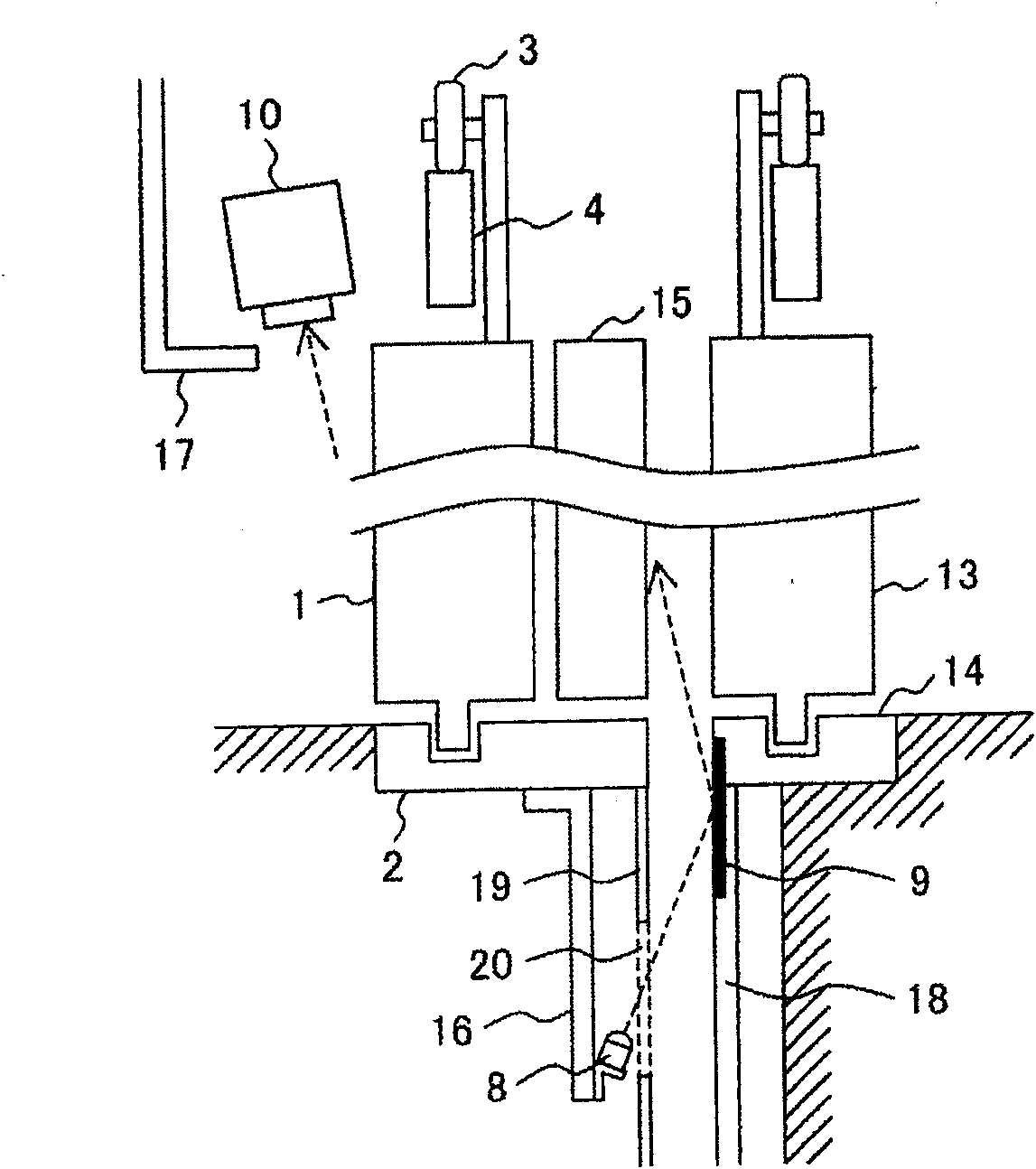
[0080] Figure 7 It is a schematic diagram showing the structure of an elevator safety device according to the second embodiment of the present invention.
[0081] Such as Figure 7 As shown, the central split elevator door adopting the safety device of this embodiment has the same figure 1 The same structure and control device. versus figure 1 The difference is that in this embodiment, as the light emitting device, in addition to the light emitting device 8 provided between the door sill of the elevator door on the car side and the door sill of the elevator door on the hall side, it also has the light emitting device 8 provided on the elevator door on the car side. The second light-emitting device 7a between the elevator door and the hall side elevator door and the third light-emitting device 7b provided on the elevator car side and located below the elevator car door when fully opened, the third light-emitting device 7b is used for the elevator car The gap between the side and the elevator lobby side is continuously illuminated. Such as Figure 7 As shown, the light emitting device 7b is arranged to be located at the lower part of the threshold on the extension line of the light emitting device 7a when the elevator door is opened. The light-emitting devices 7a, 7b and the light-emitting device 8 can continuously illuminate the gap between the elevator car side and the elevator hall side.
[0082] Figure 8 It is a perspective side view of the positional relationship of the light emitting devices 7a, 7b related to the second embodiment of the present invention from the elevator lobby side. Figure 8 The elevator door 13 on the lobby side is omitted in Picture 9 It is a schematic diagram of the positional relationship of the light emitting device 7a provided between the elevator door on the car side and the elevator door on the hall side viewed from above the elevator door.
[0083] The light emitting device 7a provided between the elevator door on the car side and the elevator door on the hall side and the light emitting device 7b provided under the elevator door on the car side will be described in detail below with reference to the above-mentioned drawings.
[0084] The light emitting device 7a is installed between the elevator door 1 on the car side and the elevator door 13 on the hall side. In this embodiment, the light emitting device 7a is installed on the elevator door safety shoe 15 and the safety shoe 15 on the back side of the elevator door 1 on the car side. The position where the support mechanism interferes. The light emitted from the light emitting device 7a is reflected to the camera 10 (not shown) by the light reflecting member 22 provided on the back side of the elevator door 13 on the hall side. The light-emitting devices 7a are arranged parallel to the front end surface of the elevator door. Specifically, the light-emitting devices 7a are linearly arranged in a line along the vertical direction over the entire height range from the height of the floor surface to the range where the camera can enter the field of view. .
[0085] In addition, as a modified example, when the light-emitting device 7a is provided on the back of the elevator door 13 on the hall side, the light-emitting device 7a is provided at the position of the light reflecting member 22 shown in the figure, so that the light reflecting member may not be provided. As a structural example of the light reflecting member 22, it is similar to the light reflecting member 9 ( figure 2 ) Is the same, and examples include a reflector with a specular reflective surface, a reflector with a white surface, and a reflector with a phosphor.
[0086] The light emitting device 7b is provided to continuously illuminate the gap between the elevator car side and the elevator hall side of the elevator door and the threshold. The light-emitting device 7b is installed at a position located at the lower part of the threshold on the extension line of the second light-emitting devices 7a arranged linearly in a row with the elevator door opened. The orientation of the light-emitting device 7b is adjusted so that the light of the light-emitting device 7b can continuously illuminate the part located between the light-emitting device 7a and the light of the light-emitting device 8, and the light of the light-emitting device 7b can pass through and be installed in the lobby The light reflecting member 22 on the back side of the side elevator door reflects into the camera 10. The light-emitting devices 7a, 7b and the light-emitting device 8 can continuously illuminate the gap between the elevator car side and the elevator hall side.
[0087] In the above description, the case where the light emitting devices 7a, 7b and the light emitting device 8 are installed on the side of the elevator car and the case where they are installed on the side of the elevator lobby have been described. When the light-emitting devices 7a, 7b and the light-emitting device 8 are installed on the side of the elevator lobby, they need to be installed on all floors where the elevator stops, and installation and maintenance operations are time-consuming and labor-intensive. Therefore, it is preferable to install the light emitting devices 7a, 7b and the light emitting device 8 on the side of the elevator car.
[0088] Picture 10 with Picture 11 Respectively and Figure 5 with Image 6 Correspondingly, an example of an image of the foreign object detection operation according to the second embodiment is shown.
[0089] In the first embodiment, only the part of the elevator upper and lower entrance between the elevator lobby and the elevator car, which is located above the threshold, is illuminated. Therefore, if the pet leash is Image 6 When the light-emitting part 62 is more outside, the possibility that the pet leash will not be detected increases.
[0090] To solve this problem, according to the second embodiment, the light-emitting device 7a, 7b and the light-emitting device 8, such as Picture 11 As shown, not only the gap of the threshold of the elevator door is illuminated, but also the gap of the front end surface of the elevator door is continuously illuminated. As a result, it can be detected not only when the pet leash is located in the gap of the elevator door threshold, but also when the pet leash 61 is Picture 11 As shown, when it exists against the front end surface of the elevator door in a suspended state, the light-emitting part 64 can be reliably blocked and/or partially missing. By detecting the blocking and/or partial missing, it is possible to avoid the rope The rope 61 is detected under the influence of the brightness of 61 and the surrounding lighting conditions.
[0091] By adopting the above-mentioned method for foreign body detection, even when the rope-shaped foreign body with a small diameter is in contact with the front end surface of the elevator door, it can be detected. That is to say, whether the rope-shaped foreign body or the band-shaped rope-shaped foreign body is in It can be detected in any position.
[0092] The following reference Picture 12 , Figure 13 as well as Figure 15 The operation of the entire elevator equipment according to an embodiment of the present invention including the operation of the elevator will be described.
[0093] Such as Picture 12 As shown, after the elevator car reaches the destination floor, the elevator control device 6 issues an instruction to the elevator door control device 5 to open the elevator door 1 (S1, S2). After a predetermined time has passed, or when the door closing button in the elevator car is operated, an instruction to close the elevator door is issued to the elevator door control device 5 (S3, S4). Then, after confirming that the elevator door 1 is normally closed, the elevator car starts to move toward the next destination floor (S5, S6).
[0094] Such as Figure 13 As shown, the elevator door control device 5, for example, receives an instruction from the elevator control device 6 to close the elevator door 1, and then issues a foreign object detection start instruction to the foreign object detection control unit 12 (S10, S11). When the result of foreign body detection indicates that there is a foreign body, a voice prompt urging the passenger to remove the foreign body is issued, or a warning sound is issued (S12, S13). Then, the light emitting device corresponding to the position where the foreign object is detected is caused to emit light (S14). Then, the foreign body detection process is repeated until the foreign body is removed. During this period, voice prompts or warning sounds are continued or the light-emitting device is flashed. And after the foreign matter is removed, the elevator doors are closed (S12, S15).

PUM

no PUM

Description & Claims & Application Information

We can also present the details of the Description, Claims and Application information to help users get a comprehensive understanding of the technical details of the patent, such as background art, summary of invention, brief description of drawings, description of embodiments, and other original content. On the other hand, users can also determine the specific scope of protection of the technology through the list of claims; as well as understand the changes in the life cycle of the technology with the presentation of the patent timeline. Login to view more.

Similar technology patents

Classification and recommendation of technical efficacy words

  • Low cost
  • Reduce intensity

Semiconductor device

InactiveUS6975142B2Low costReduce manufacturing stepsTransistorSolid-state devicesVoltage amplitudeSemiconductor
Owner:SEMICON ENERGY LAB CO LTD

Dimming mirror with blind zone sub-mirror and indicator

ActiveUS6919796B2Reduce light intensityReduce intensityMirrorsAnti-collision systemsComputer visionWing mirror
Owner:MAGNA MIRRORS OF AMERICA
Why Eureka
Try Eureka