Shaft for wind turbine generator and method for assembling wind turbine generator

A wind turbine, wind turbine technology, applied in the direction of wind motor combination, wind engine, wind engine consistent with the wind direction, etc., to achieve the effect of low material cost

Inactive Publication Date: 2010-11-24
GENERAL ELECTRIC CO
View PDF4 Cites 2 Cited by
  • Summary
  • Abstract
  • Description
  • Claims
  • Application Information

AI Technical Summary

Problems solved by technology

The first strength property value is greater than the second strength property value

Method used


Image

  • Shaft for wind turbine generator and method for assembling wind turbine generator
  • Shaft for wind turbine generator and method for assembling wind turbine generator
  • Shaft for wind turbine generator and method for assembling wind turbine generator

Examples


Embodiment Construction

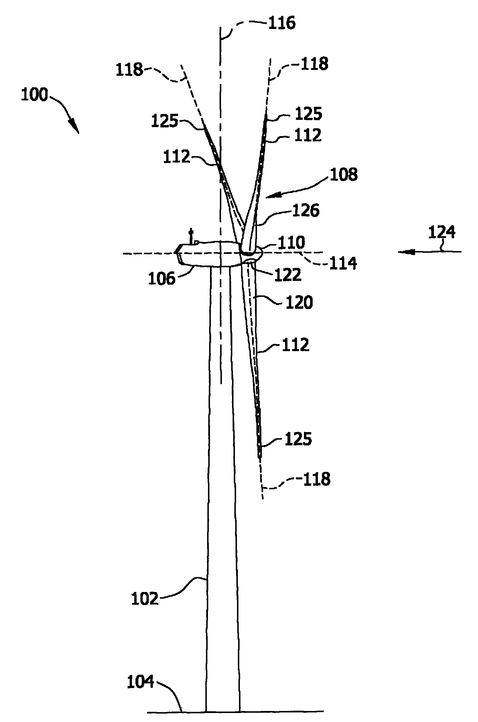
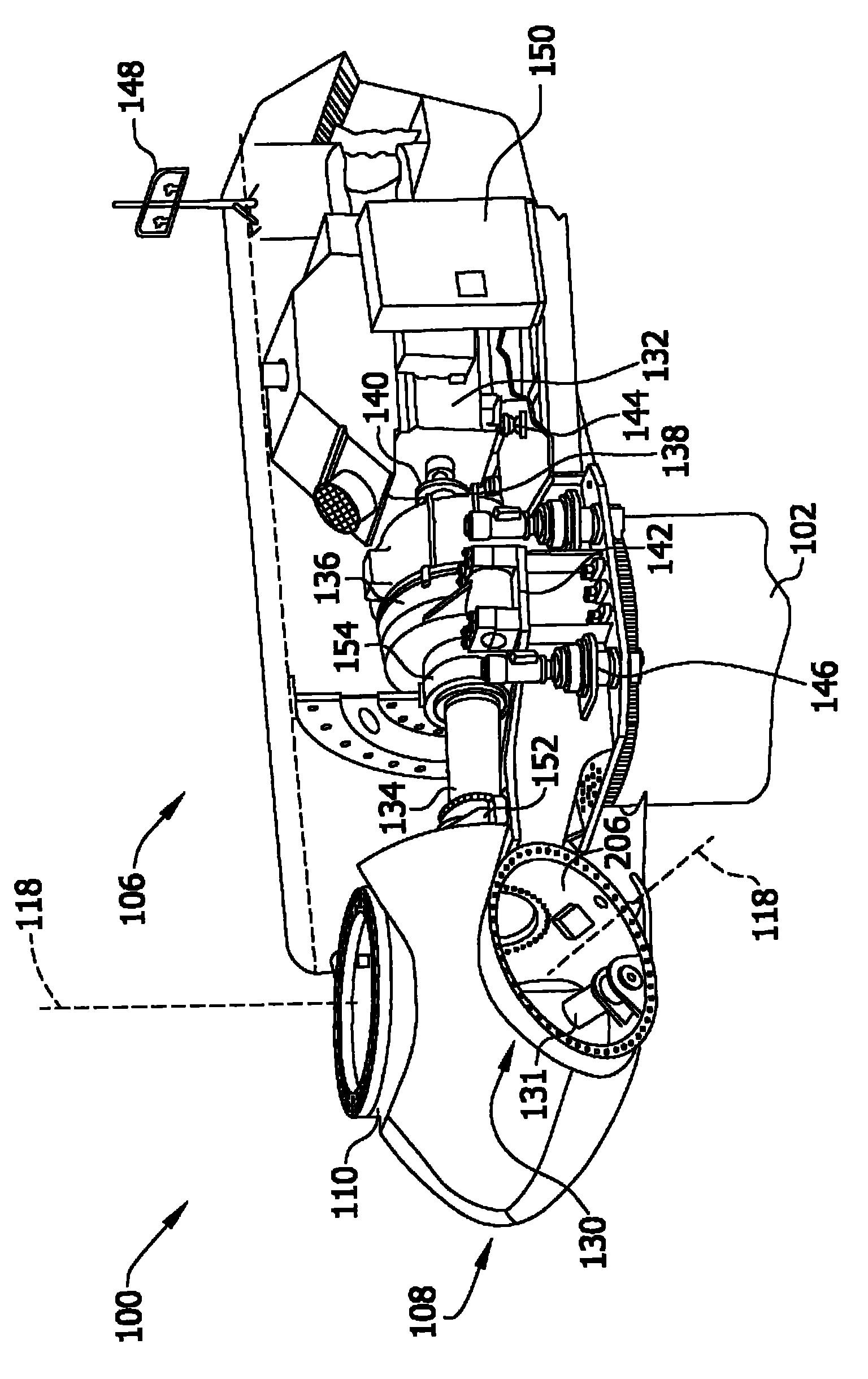
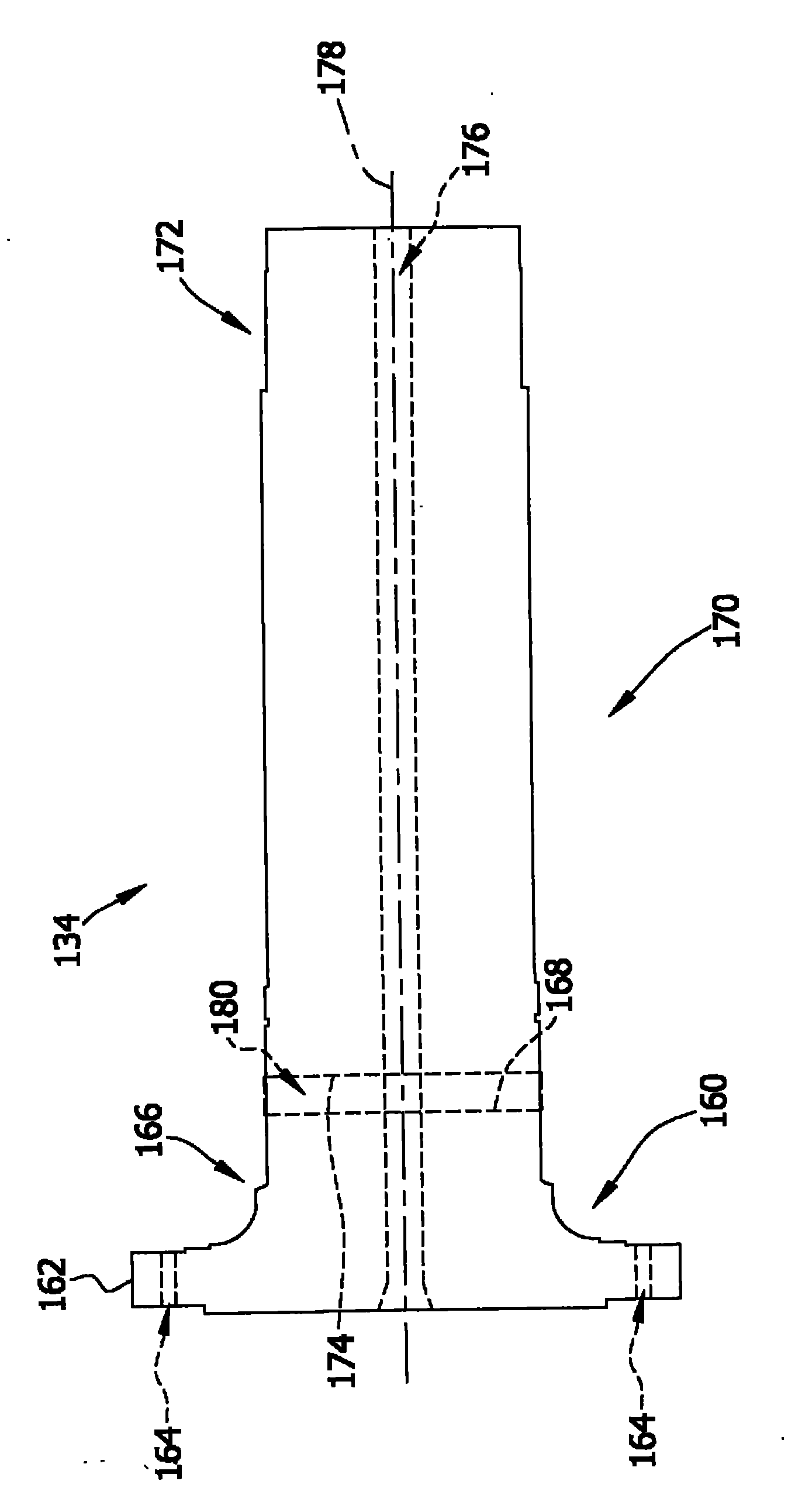
[0098] The methods and rotor shafts described herein facilitate the assembly of wind turbine generators by using a stronger, more robust steel alloy in the forward portion of the rotor shaft, which is typically subjected to higher stresses and loads. In contrast, a lower strength, less robust steel alloy is used in the rear portion of the rotor shaft, which is typically subjected to lower stresses and loads. The front and rear of the rotor shaft are welded by flash welding, narrow groove tungsten electrode inert gas welding (GTAW), gas metal arc welding (GMAW), flux cored arc welding (FCAW), laser beam welding, composite At least one of laser beam welding, resistance welding and friction welding to be welded to each other. In particular, the technical effect of manufacturing two separate parts of the rotor shaft provides an opportunity for cost savings due to the need for smaller forging equipment and smaller machining equipment, as well as separate suppliers for each part. A...


PUM

PropertyMeasurementUnit
diameteraaaaaaaaaa
diameteraaaaaaaaaa
diameteraaaaaaaaaa

Abstract

A wind turbine rotor (108) includes a first portion (160) of a shaft (134) fabricated from a first steel alloy having a first strength property value. The wind turbine rotor also includes a second portion (170) of the shaft fabricated from a second steel alloy having a second strength property value. The first strength property value is greater than the second strength property value. The second portion of the shaft is welded to the first portion of the shaft.

Description

technical field [0001] The subject matter described herein relates generally to wind turbine generators, and more particularly to a method and shaft for facilitating assembly of a wind turbine generator. Background technique [0002] At least some known wind turbine generators include a rotor with a plurality of blades. The rotor is often coupled to a casing or nacelle positioned atop a foundation (eg, a truss or tubular tower). At least some known utility-grade wind turbines (ie, wind turbines designed to provide electrical power to a utility grid) have rotor blades with predetermined shapes and dimensions. The rotor blades transform the mechanical wind energy into an induced blade lift force which in turn produces a mechanical torque which drives one or more generators via the rotor shaft, which in turn produces electricity. The generator is often, but not always, rotatably coupled to the rotor shaft through a gearbox. The gearbox steps up the inherently low rotational ...

Claims


Application Information

Patent Timeline
Patent Type & Authority Applications(China)
IPC IPC(8): F03D1/06F16C3/02F03D9/00
CPCB23K20/122B23K26/1423B23K9/025B23K9/167B23K2201/006B23K26/1429F05B2230/232B23K28/02B23K9/173F05B2230/239F03D1/06F05B2280/10302F05C2201/0466F05C2201/0406F05C2201/0409F05B2240/60B23K26/265Y02E10/721F05B2280/10303F16C2360/31B23K26/262F16C3/023B23K26/348B23K2101/006F16C2226/36Y10T29/49316Y02E10/72Y02P70/50
Inventor S·萨蒂安B·S·贝奇帕利
Owner GENERAL ELECTRIC CO
Why Eureka
Try Eureka