
Hose coupler

A hose joint and a technology for connecting hoses, applied in the field of pipe joints, can solve the problems of connection strength, tightness, cumbersome and laborious loading and unloading operations, etc.

Active Publication Date: 2010-11-24
DONGFANG ELECTRIC MACHINERY
View PDF5 Cites 20 Cited by
  • Summary
  • Abstract
  • Description
  • Claims
  • Application Information

AI Technical Summary

Problems solved by technology

The connection methods of hoses are generally connected by iron wire binding or pipe clamps (including extruded pipe clamps and screw-tensioned pipe clamps). The common feature of these three connection methods is that the bundled or clamped hoses produce Inner shrinking extrusion deformation is realized by the anti-slip friction resistance between the inner surface of the hose or the inner surface of the inner tube and the outer surface of the connecting tube core (inverted tapered pipe joint or smooth straight pipe joint with large and small head diameters) For sealing and connection, the connection force is only generated on the inner surface of the pipe. Without the use of special tooling and tools, the connection strength and sealing performance are not easy to guarantee, easy to leak, or even fall off, and the loading and unloading operations are cumbersome and laborious.

Method used


Image

  • Hose coupler
  • Hose coupler
  • Hose coupler

Examples


Embodiment Construction

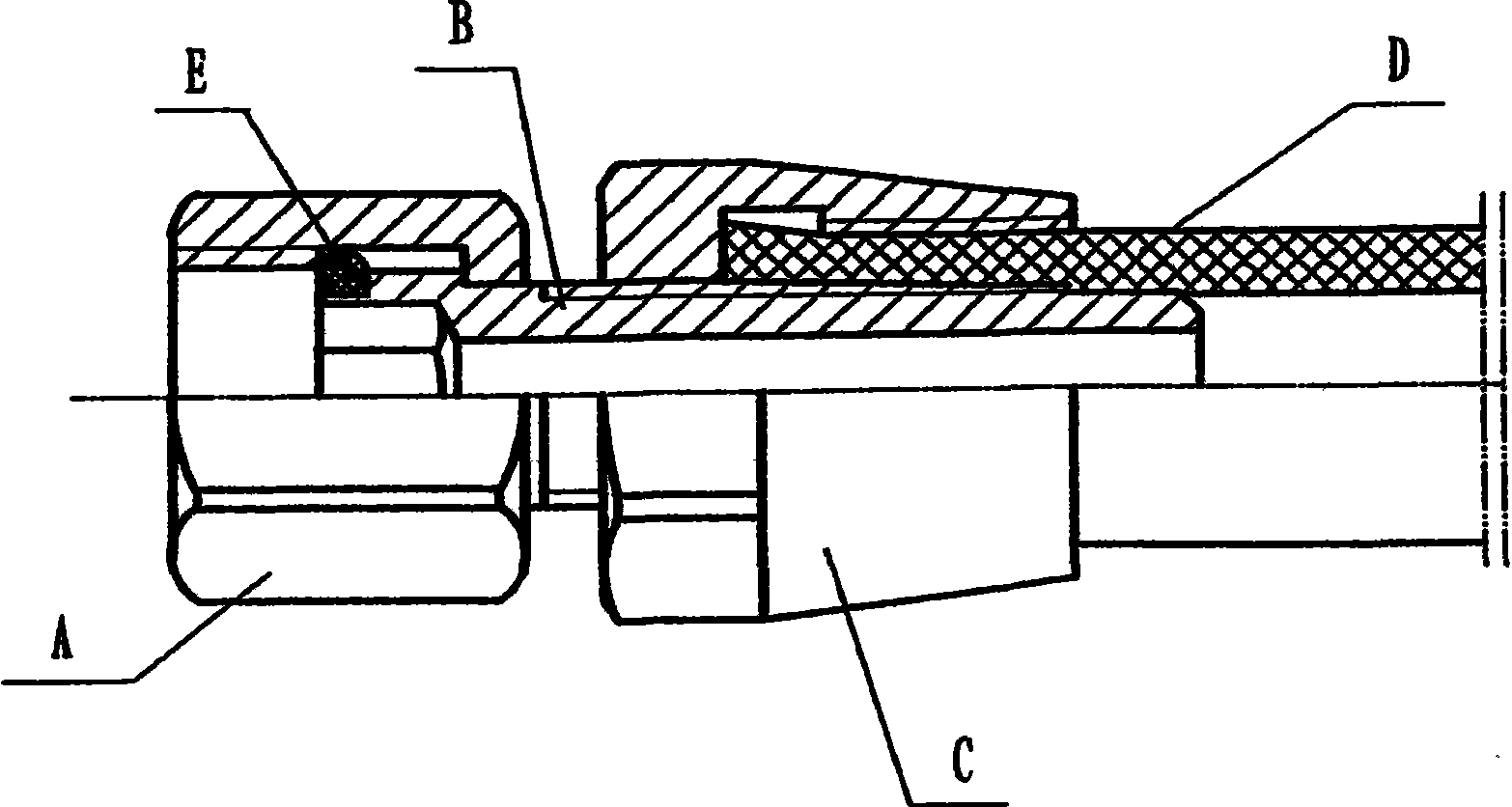
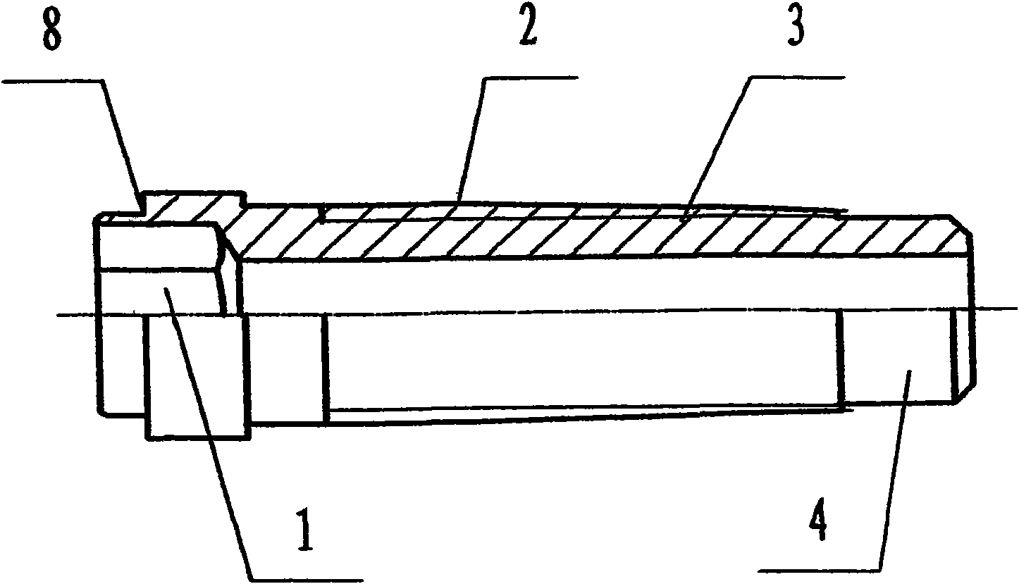
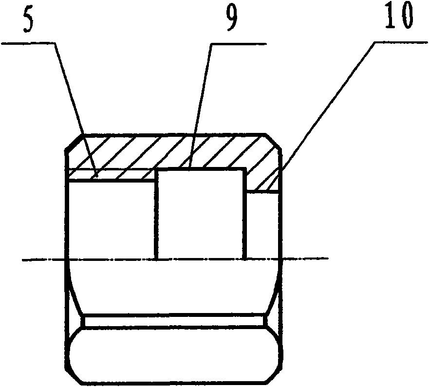
[0019] see Figure 1 to Figure 4 .

[0020] Depend on figure 1 It can be seen that the expansion collar joint is mainly composed of three parts: connecting live nut A, expansion tube bolt B and collar nut C.

[0021] see figure 2 : Expansion tube bolt B, composed of hexagon socket hole 1, pipe connection external thread 2, expansion tube external thread 3, hose guide section 4, and stepped seam 8.

[0022] The inner hexagonal hole 1 should be selected from the standard inner hexagonal hole system. The selection principle is that the diameter of the inscribed circle of the inner hexagonal hole is slightly greater than or equal to the diameter of the through hole of the expansion tube core, so as to ensure that the joint has the largest through hole medium flow.

[0023] Pipe connection external thread 2 and expander pipe external thread 3 belong to the cylindrical section and conical section of the same thread surface; the thread outer diameter of pipe connection external t...


PUM


Abstract

The invention relates to a hose coupler, composed of an expand tube bolt, a banded penstock nut and a union nut; wherein the expand tube bolt is characterized in that the outer diameters of a thread section in entire structure and a cylindrical bolt head thread section are matched with the inner diameter of the hose to be connected, the center of the bolt is provided with a longitudinal through hole, the section of the through hole is in the shape that the part corresponding to the thread section is a round hole and the part corresponding to the bolt head is a regular polygon spanner hole; the inner hole of the banded penstock nut is a stepped hole, the small diameter section is a threaded hole and is matched with the thread of the expand tube bolt, the inner wall surface of the big diameter section is a non-slip surface and is matched with the outer diameter of the hose to be connected, the hose is arranged in the clearance between the big diameter section and the thread section of the expand tube bolt; the inner hole of the union nut is a stepped hole, the small diameter section is an unthreaded hole and is emptily sheathed on the excircle surface of the thread section of the expand tube bolt, and the big diameter section is a threaded hole and is matched with the outer thread of a connected tool; and the bolt head of the expand tube bolt is arranged in the threaded hole of the union nut. The hose coupler has high joint strength and good sealing property, and no special tool is required in mounting and dismounting, operation is simple and convenient, rapid and labour-saving, and the operation can be completed in manual.

Description

technical field [0001] The invention relates to a pipe joint, specifically a hose joint, especially suitable for high-pressure working medium in daily production. Background technique [0002] In the production and operation sites of enterprises, there are often some equipment that use gas or liquid working medium. The transmission pipeline of the medium adopts hoses. This is especially true for thermal processing units with gas, compressed air and nitrogen, hydrogen, argon, carbon dioxide gas, etc. as the working medium. The connection methods of hoses are generally connected by iron wire binding or pipe clamps (including extruded pipe clamps and screw tensioned pipe clamps). The common feature of these three connection methods is that the bundled or clamped hoses have Inner shrinking extrusion deformation is realized by the anti-slip friction resistance between the inner surface of the hose or the inner surface of the inner tube and the outer surface of the connecting tub...

Claims


Application Information

Patent Timeline
IPC IPC(8): F16L33/22
Inventor 杨富永
Owner DONGFANG ELECTRIC MACHINERY
Learn More