Pulse water-cannon truck for anti-riot dispersion and control method thereof
A technology of pulse and cannon vehicles, which is applied in the field of anti-riot and dispersal pulse water cannon vehicles and its control, and can solve the problems of affecting the release speed of high-pressure gas, insufficient flexibility and mobility, and easy water leakage.
- Summary
- Abstract
- Description
- Claims
- Application Information
AI Technical Summary
Problems solved by technology
Method used
Image
Examples
Embodiment 1
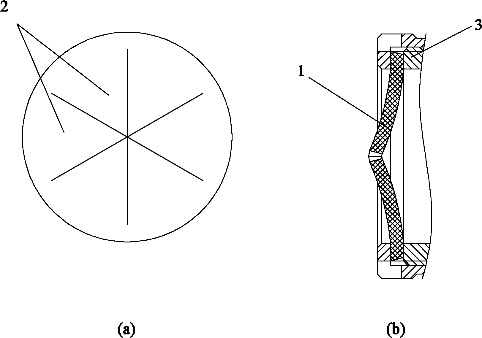
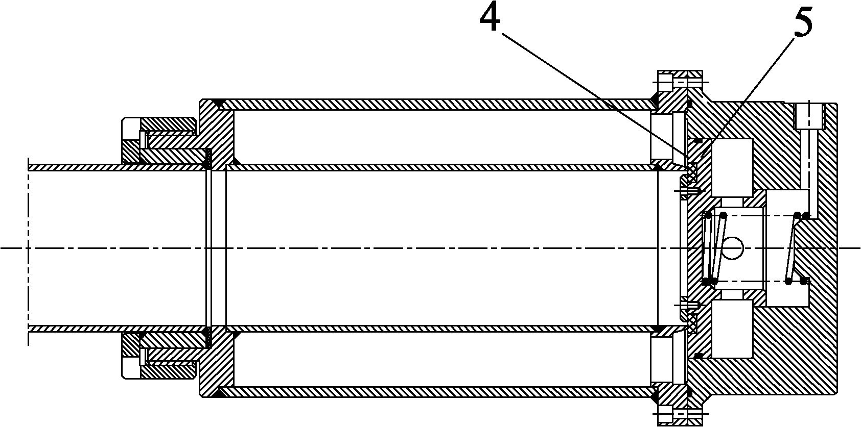
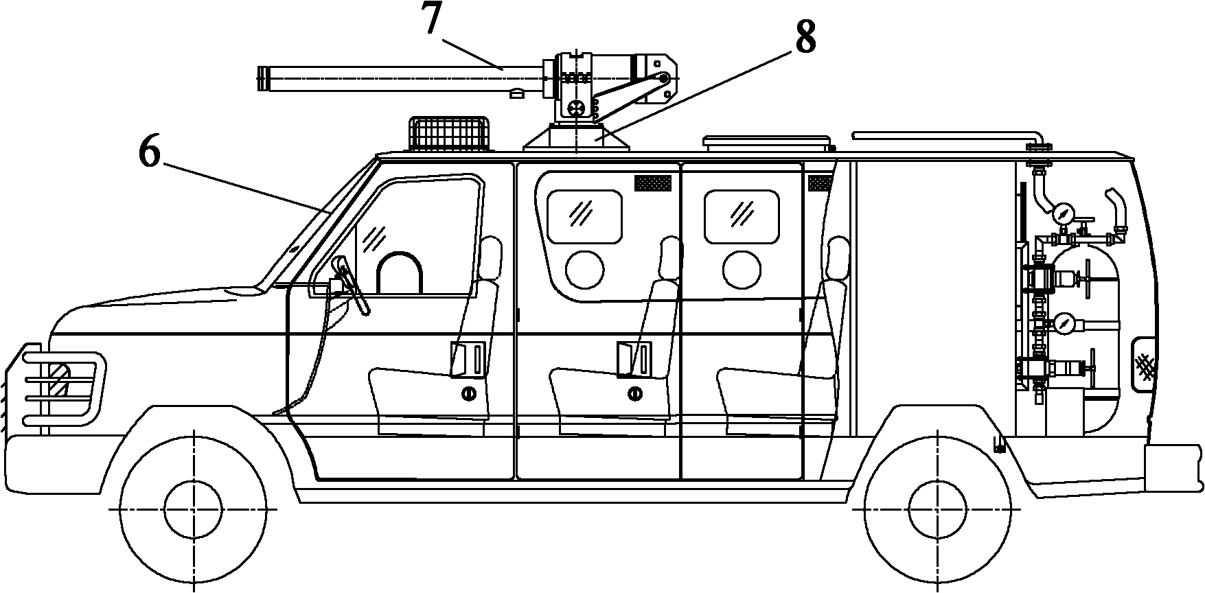
[0068] Figure 3 to Figure 9 Shows the specific structural schematic diagram of this embodiment, such as image 3 with Figure 4 As shown, the pulse water cannon vehicle used for anti-riot dispersal includes a car body 6, a cannon body 7, and a liquid supply system 9, an air supply system 10 and a control system placed inside the car body 6, and the cannon body 7 passes through the cannon body. The body mounting seat 8 is installed outside the top of the car body 6, and the cannon body 7 includes a liquid storage mechanism, a liquid-gas connection mechanism, a valve body mechanism and a gas storage mechanism, and the front end of the liquid storage mechanism is connected with a liquid sealing member 12; The liquid-gas connection mechanism is respectively connected to the liquid storage mechanism and the gas storage mechanism, the valve body mechanism is respectively connected to the liquid-gas connection mechanism, the liquid storage mechanism and the gas storage mechanism, a...
Embodiment 2
[0104] Present embodiment except following feature other structures are with embodiment 1: as Figure 10 As shown, the valve body mechanism includes a valve body 58 and a main valve and a secondary valve placed in the valve body 58. The main valve includes a main valve cylinder 53, a main valve piston 52 and a main valve spring 60. The main valve cylinder The front end and the rear end of 53 are respectively provided with a groove cavity; the main valve piston 52 and the main valve spring 60 are placed in the groove cavity at the front end of the main valve cylinder 53, and the main valve cylinder 53 is connected with the main valve piston 52; One end of the main valve piston 52 is connected with the liquid-gas connection mechanism (liquid-gas connection plate 14) through the seal ring 71, and the other end is connected with the main valve cylinder 53 through the main valve spring 60, and the main valve cylinder 53 is connected with the liquid-gas connection. mechanism (liquid...
Embodiment 3
[0109] The structure of this embodiment is the same as that of Embodiment 2 except for the following features: the valve body mechanism includes a valve body, a main valve and two auxiliary valves placed in the valve body, and the structure of the main valve and each auxiliary valve is the same as that of Embodiment 2.
[0110] The auxiliary valves are correspondingly connected through the auxiliary valve gas channel and the unloading channel. Each auxiliary valve corresponds to a control air port, a check valve, six auxiliary valve gas passages and six unloading passages.
PUM
 Abstract
Description
Claims
Application Information
 - R&D
- Intellectual Property
- Life Sciences
- Materials
- Tech Scout
- Unparalleled Data Quality
- Higher Quality Content
- 60% Fewer Hallucinations
Browse by: Latest US Patents, China's latest patents, Technical Efficacy Thesaurus, Application Domain, Technology Topic, Popular Technical Reports.
© 2025 PatSnap. All rights reserved.Legal|Privacy policy|Modern Slavery Act Transparency Statement|Sitemap|About US| Contact US: help@patsnap.com


