
Scintillator and scintillator detector

A scintillator and detector technology, applied in the field of scintillators and scintillator detectors, can solve the problems affecting the accuracy of experimental results, signal acquisition and analysis interference, signal time broadening and widening, etc., to reduce the average optical path, The effect of reducing the cost and reducing the optical path difference

Inactive Publication Date: 2010-11-24
INST OF HIGH ENERGY PHYSICS CHINESE ACADEMY OF SCI
View PDF4 Cites 1 Cited by
  • Summary
  • Abstract
  • Description
  • Claims
  • Application Information

AI Technical Summary

Problems solved by technology

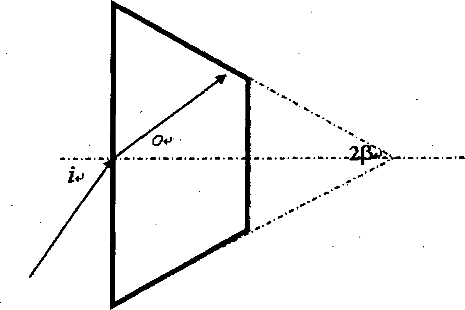
It can be found that the smaller the apex angle of the cone, the more favorable the reflection of light from the large end to the small end, but to converge to a suitable area, the required light cone size is larger, resulting in a larger average optical path and optical path difference, resulting in signal At the same time, due to the multiple reflections of light inside the scintillator and the self-absorption of the scintillator, it will cause light loss, which will interfere with the collection and analysis of the signal and affect the accuracy of the experimental results.
Moreover, in the process of reflection, due to the continuous decrease of the incident angle, there may be a situation where the light is reversed to the large end face, and the impact on the signal is more prominent

Method used


Image

  • Scintillator and scintillator detector
  • Scintillator and scintillator detector
  • Scintillator and scintillator detector

Examples


Embodiment Construction

[0029] The present invention will be described in detail below in conjunction with specific embodiments with reference to the accompanying drawings, but it should not be construed as a limitation of the present invention.

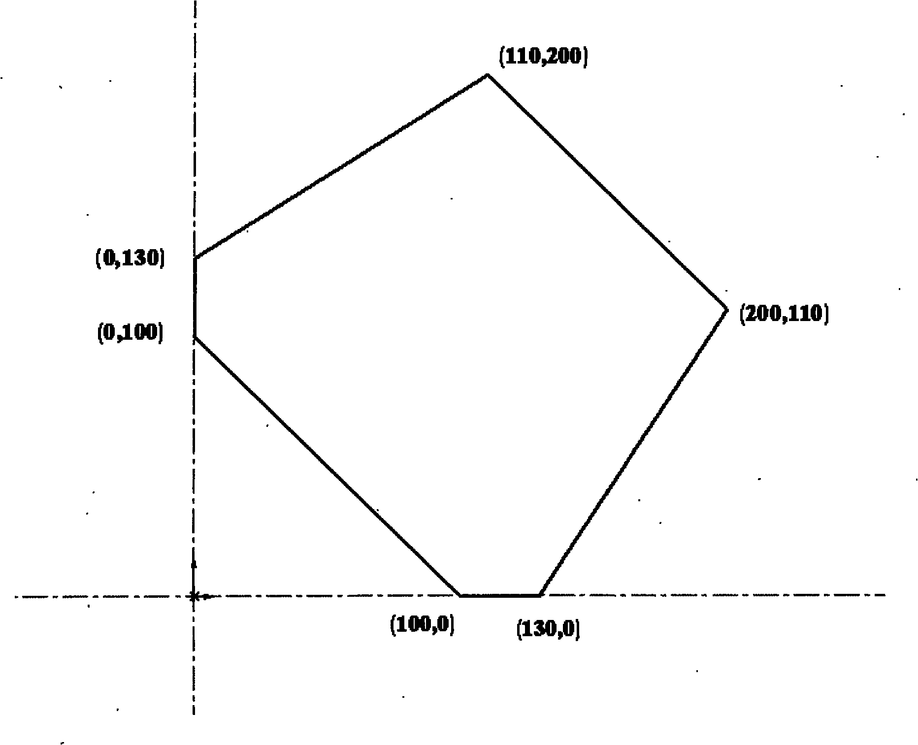
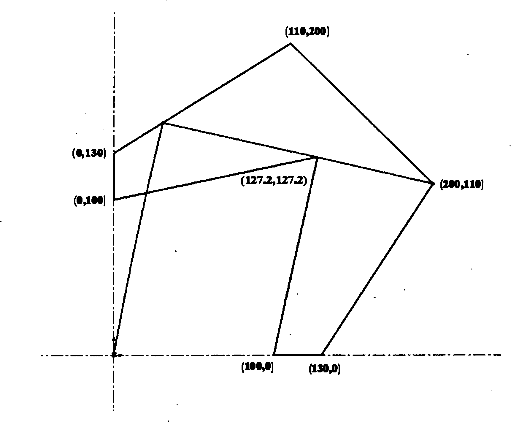
[0030] like Figure 4 Shown is a schematic cross-sectional view of a scintillator according to an embodiment of the present invention. The cross section of the scintillator is approximately trapezoidal, and a reflective groove is provided on the scintillator. The opening end of the reflective groove is located on the large end surface of the scintillator, and its width is from the large end surface of the scintillator to its small end surface. Tapered to a V-shape. The gamma energy generated by the annihilation of o-Ps is between 0-511keV. In order to make all the low-energy gamma that does not undergo the scintillation process propagate to the upper end surface, and at the same time, make the fluorescence emitted by the high-energy gamma through the scint...


PUM


Abstract

The invention discloses a scintillator and a scintillator detector including the scintillator. The scintillator with the section approximate to trapezoid is provided with a reflection groove, an opening end of which is positioned at a large end face of the scintillator, and the width of the opening end gradually diminishes from the large end face to a small end face of the scintillator. According to the invention, a reflection face is added by means of the arrangement of the reflection groove, thereby reducing average optical path of lights, enhancing proportion of effective signals and raising detection efficiency of the detector; in addition, optical path difference of lights is reduced, the full width at half maximum (FWHM) and one-tenth height and width of signals are lessened, so time resolution of the detector is enhanced; and the scintilator and the scintillator detector also save material and lower cost.

Description

technical field [0001] The invention relates to a scintillator and a scintillator detector, in particular to a scintillator and a scintillator detector with reflection grooves. Background technique [0002] Positron annihilation technology can non-destructively detect the microscopic defect information near the surface of materials, and is an effective means to analyze the properties of materials. In the positronium time-of-flight spectroscopy (Ps-TOF) measurement method, the relevant information of the material is mainly obtained through the o-Ps flying out of the material surface. Or triple gamma annihilation, the resulting gamma is emitted at a 4π solid angle. For Ps-TOF, the main thing to collect is the gamma whose emission direction is perpendicular to the positronium flight axis. Therefore, it is only necessary to emit The γ can be collected. In order to obtain as much information as possible, the collection efficiency of the γ emitted at an angle of 2π in the plane ...

Claims


Application Information

Patent Timeline
Patent Type & Authority Applications(China)
IPC IPC(8): G01T1/20
Inventor 姜小盼曹兴忠秦秀波李卓昕于润升王宝义魏龙
Owner INST OF HIGH ENERGY PHYSICS CHINESE ACADEMY OF SCI
Learn More