Plasma display panel

A plasma display and panel technology, applied in the direction of AC plasma display panels, gas discharge tubes/containers, electrical components, etc., can solve the problems of electron emission performance reduction, charge decay rate, charge retention performance, etc.

Inactive Publication Date: 2010-11-24
PANASONIC CORP
View PDF1 Cites 0 Cited by
  • Summary
  • Abstract
  • Description
  • Claims
  • Application Information

AI Technical Summary

Problems solved by technology

In this way, there is a problem that as a characteristic of the protective layer, it is necessary to simultaneously maintain two opposite characteristics of high electron emission performance and high charge retention performance that reduces the charge decay rate as a memory function.

Method used


Image

  • Plasma display panel
  • Plasma display panel
  • Plasma display panel

Examples


Embodiment approach

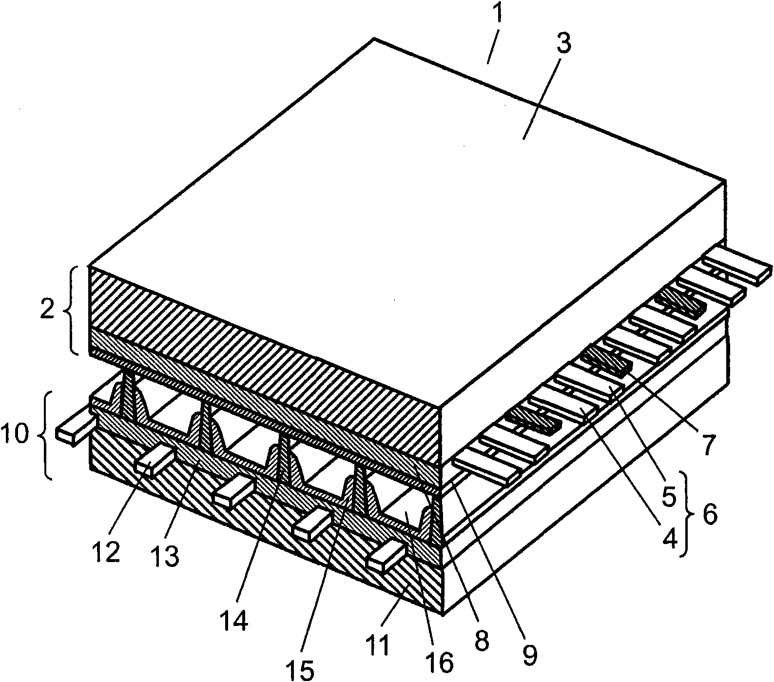
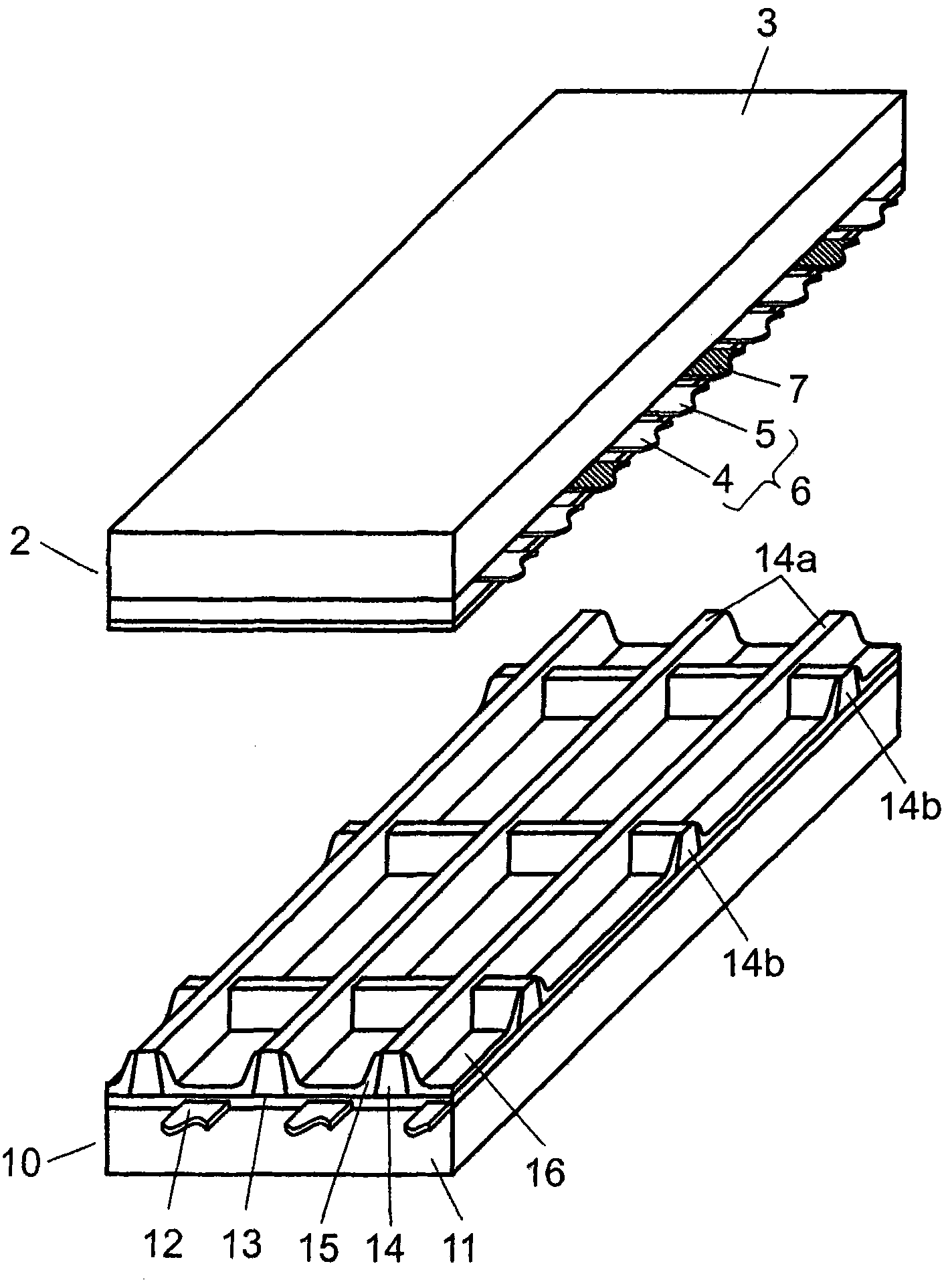
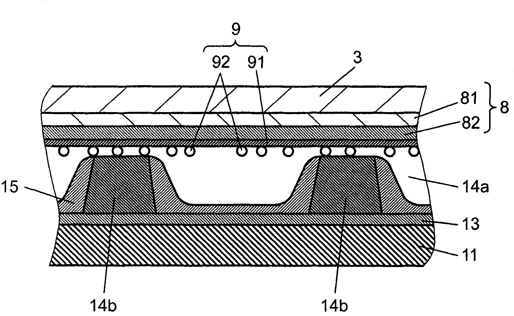
[0052] figure 1 It is a perspective view showing the structure of the PDP in the embodiment of the present invention. figure 2 It is a perspective view showing a front panel and a rear panel separately. image 3 is a cross-sectional view showing the cross-sectional structure of the discharge cell portion.

[0053] Such as figure 1 As shown, the PDP 1 is arranged such that a front panel 2 including a front glass substrate 3 and the like faces a rear panel 10 including a rear glass substrate 11 and the like. The outer peripheral portion of the PDP 1 is sealed with a sealing material made of glass frit or the like. Discharge gases such as Ne and Xe are sealed in the discharge space 16 inside the sealed PDP 1 at a pressure of 400 Torr to 600 Torr.

[0054] On the front glass substrate 3 of the front panel 2, a plurality of display electrodes 6 composed of a pair of strip-shaped scan electrodes 4 and sustain electrodes 5 and black stripes (light shielding layers) 7 are arrange...


PUM


Abstract

A plasma display panel is provided with a front substrate which has a dielectric layer formed to cover a display electrode formed on a front glass substrate, and has a protection layer formed on the dielectric layer; and a rear substrate, which is arranged to face the front substrate so as to form a discharge space and to form an address electrode formed in a direction that intersects the display electrode, and is provided with a plurality of vertical barrier ribs and horizontal barrier ribs which are arranged parallel to the address electrode. The protection layer forms a base film on the dielectric layer, and the protection layer is configured by adhering a plurality of crystal grains composed of a metal oxide such that the crystal grains are distributed over the entire surface of the base film. The barrier ribs are configured such that the horizontal barrier ribs are lower than the vertical barrier ribs.

Description

technical field [0001] The present invention relates to a plasma display panel used in a display device and the like. Background technique [0002] Plasma display panels (hereinafter referred to as "PDP") are widely used in 65-inch type televisions and the like because they can achieve high definition and large screen size. In recent years, compared with the existing NTSC system, PDP has been developed to be suitable for high-definition televisions with twice or more scanning lines, and in consideration of environmental issues, lead-free PDPs are required. [0003] A PDP basically consists of a front panel and a rear panel. The front panel is composed of a glass substrate of sodium borosilicate glass obtained by a float process; a display electrode consisting of stripe-shaped transparent electrodes and bus electrodes formed on one main surface of the glass substrate; a dielectric layer, which covers the display electrodes and functions as a capacitor; and a protective laye...

Claims


Application Information

Patent Timeline
Patent Type & Authority Applications(China)
IPC IPC(8): H01J11/02H01J9/02H01J11/22H01J11/24H01J11/34H01J11/36H01J11/40
CPCH01J11/40H01J11/12H01J11/36
Inventor 盐川晃沟上要石野真一郎坂元光洋加道博行大江良尚河原崎秀司上谷一夫
Owner PANASONIC CORP
Why Eureka
Try Eureka