
Micro-gas generator with closed cavity

A closed cavity and generator technology, applied in the direction of machines/engines, mechanical equipment, etc., can solve the problems of complex structure, unsuitable for miniaturization, unsuitable for renewable energy, etc., and achieve the effect of low cost and replacement

Inactive Publication Date: 2010-12-01
BEIJING WISWORD HI TECH
View PDF6 Cites 2 Cited by
  • Summary
  • Abstract
  • Description
  • Claims
  • Application Information

AI Technical Summary

Problems solved by technology

However, their structure is complex. For large-scale steam turbine power generation, it is not suitable for miniaturization, while ordinary power generation equipment that can be miniaturized requires traditional energy, such as diesel for combustion, and is not suitable for renewable energy. A type of external combustion engine

Method used


Image

  • Micro-gas generator with closed cavity
  • Micro-gas generator with closed cavity
  • Micro-gas generator with closed cavity

Examples


Embodiment 1

[0038] Embodiment 1, Natural Gas Closed Cavity Miniature Gas Generator

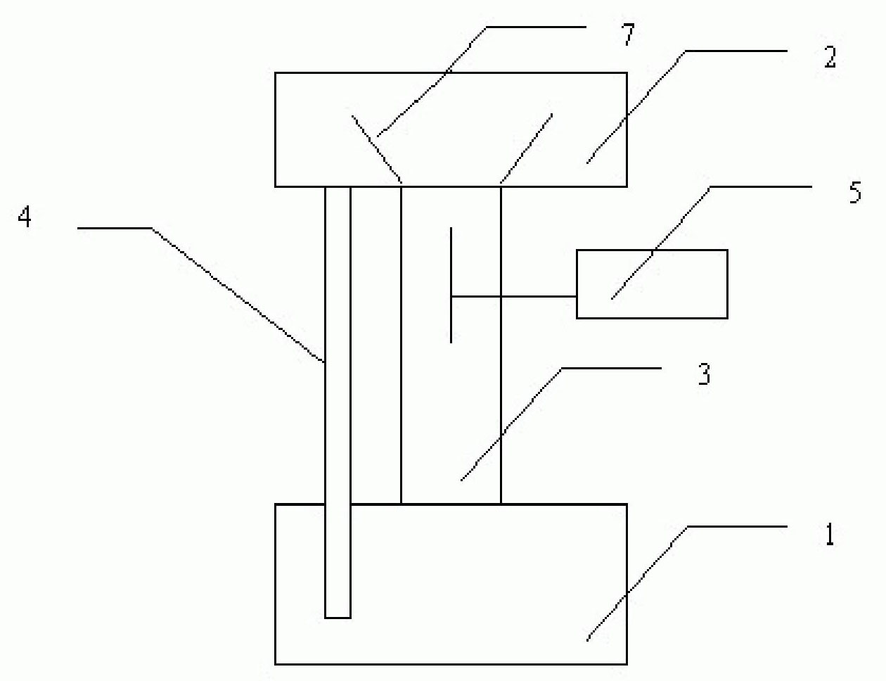
[0039] figure 1 The middle evaporation chamber 1 is heated by the external natural gas to evaporate the internal working medium 10. The evaporated gas enters the impeller area through a narrow channel, and after being sprayed, the impeller is driven to rotate. The exhausted steam enters the condensation chamber 2 and passes through the condensation chamber 2. After condensation, it enters the liquid return pipeline 4, and then goes to the evaporation chamber 1 through the liquid return pipeline 4 to realize cycle power generation.

Embodiment 2

[0040] Embodiment 2, solar energy closed cavity micro-gas generator with fins

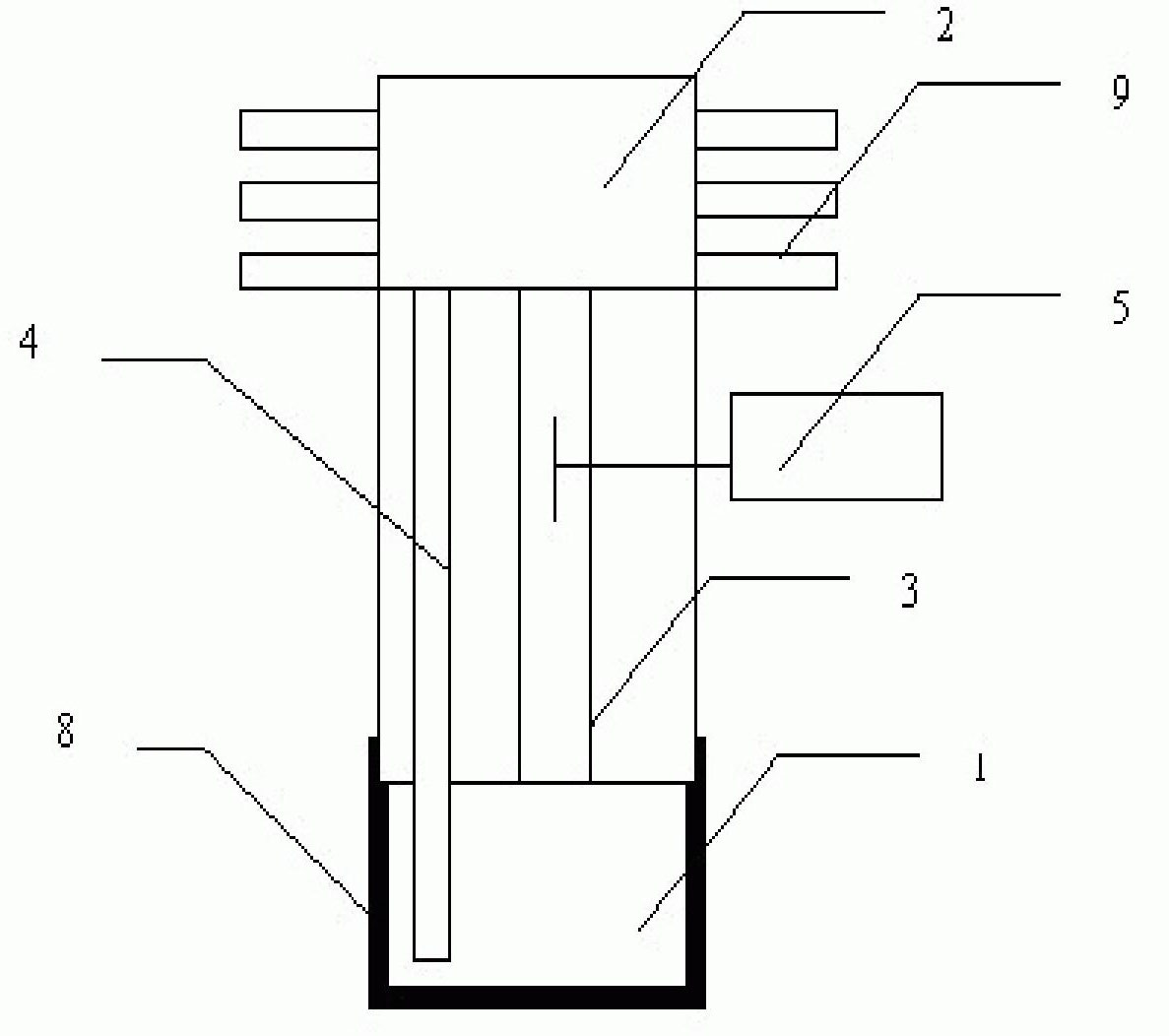
[0041] Put the selective coating 8 on the outside of the evaporation chamber 1, and generate heat energy under the irradiation of solar energy. The heat energy heats the internal working medium 10. After the working medium is vaporized, it drives the impeller through the narrow channel 3, and the rotation of the impeller drives the rotor to rotate to generate electricity. Fins 9 are arranged outside the chamber 2 to increase its condensation efficiency. After the working medium is condensed, the liquid is transported to the evaporation chamber 1 through the liquid return pipe 4 to realize cycle power generation.

Embodiment 3

[0042] Embodiment 3, the closed cavity micro-gas generator with heat pipe

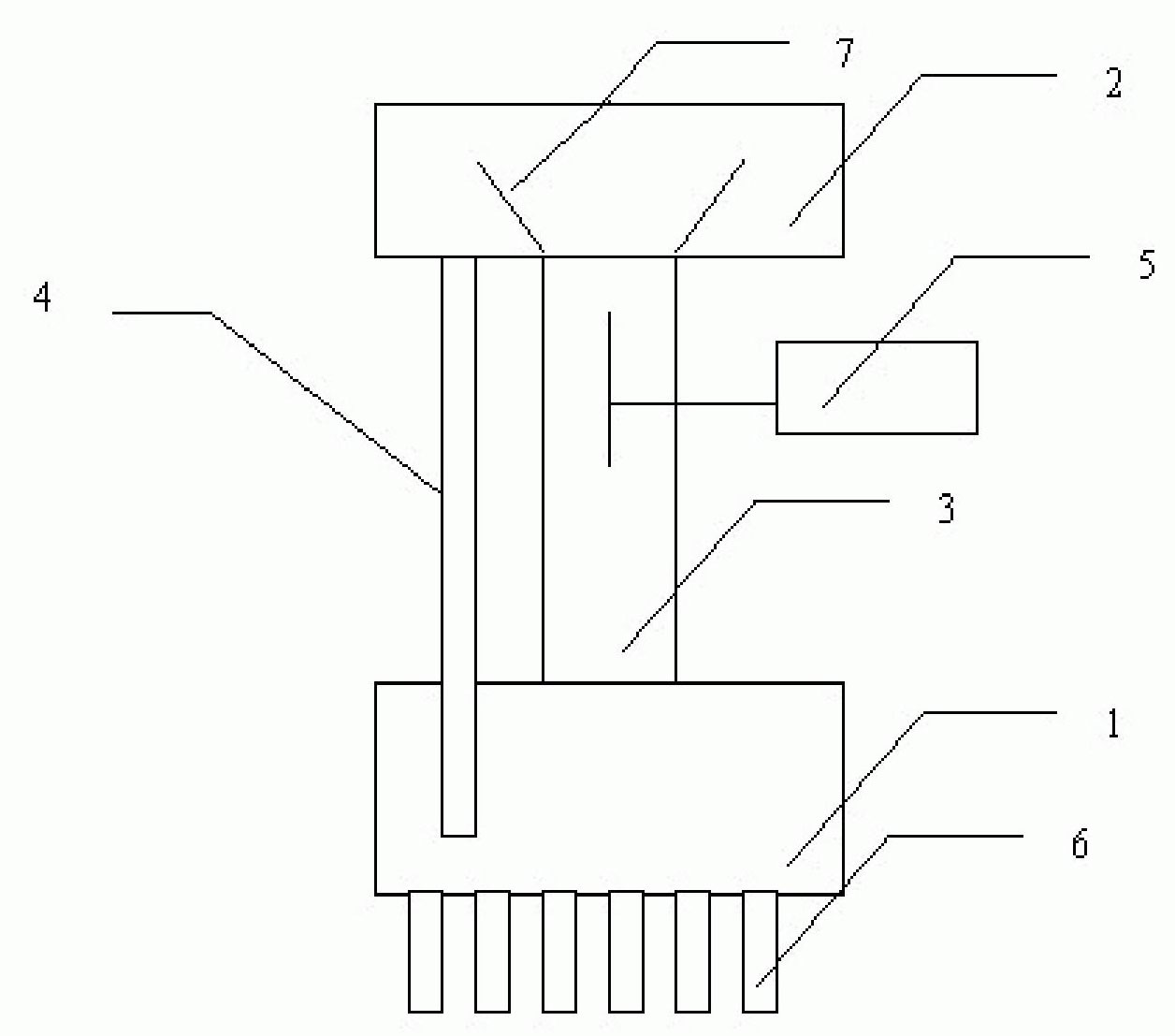
[0043] In this embodiment, the condensing section in the evaporation chamber is directly arranged in the liquid or gas area 11, and the heat is provided with a heat pipe through the heat exchange of the liquid in the condenser 3, and the heat pipe can be directly connected with various waste heat and with The temperature of the gas is exchanged, and the heat energy directly heats the liquid in the evaporation chamber, and after the vaporization is realized, the steam turbine is driven to generate electricity.


PUM


Abstract

The invention provides a micro-gas generator with a closed cavity, which comprises an evaporating chamber and a condensing chamber, wherein the evaporating chamber is connected with the condensing chamber through a narrow section, an impeller is arranged on the narrow section, the impeller is provided with a rotor and a stator, and the evaporating chamber carries out heat exchange with the outside to enable an internal low-temperature working medium to be gasified to push the impeller to rotate and generate electricity. In the invention, external heat energy can be used for generating electricity, and the forms of energy sources are not limited. The invention can be suitable for generating equipment of any size and is more suitable for micro-generating equipment and especially generating equipment of 1W-100kW.

Description

technical field [0001] The invention relates to a power generating device, a device for converting heat energy into electrical energy, especially a miniature power generating device. Background technique [0002] The existing power generation technology mainly uses steam as the working medium to generate electricity. The main working medium is water. The nozzles are set on the stator without movement, and the blades are set on the rotor. The steam injected by the nozzles drives the blades to rotate and generate electricity. [0003] The Rankine cycle (ORC) generator set using low-temperature organic matter is suitable for low-temperature heat sources and small-scale power generation, but it is mainly to miniaturize the existing large-scale steam power generation equipment, and its nozzle and blade settings are the same as those of large-scale ones. Such a structure setting The energy utilization of power generation is limited, and the working medium generally adopts the work...

Claims


Application Information

Patent Timeline
Patent Type & Authority Applications(China)
IPC IPC(8): F01B23/10
Inventor 李建民
Owner BEIJING WISWORD HI TECH
Learn More