
Optical fiber Bragg grating pressure sensor and corresponding measurement method thereof

An optical fiber Bragg and pressure sensor technology, which is applied in the measurement of fluid pressure using optical methods, and the measurement of force by measuring the change of optical properties of materials when they are stressed, can solve the problems of temperature cross-sensitivity and difficulty in accurately measuring pressure, etc. Achieve the effect of easy operation, solve temperature cross-sensitivity, and improve measurement accuracy

Active Publication Date: 2010-12-01
NINGBO SHANGONG CENT OF STRUCTURAL MONITORING &CONTROL ENG
View PDF4 Cites 28 Cited by
  • Summary
  • Abstract
  • Description
  • Claims
  • Application Information

AI Technical Summary

Problems solved by technology

However, in the actual engineering test of the fiber Bragg grating sensor, because the reflection center wavelength of the fiber Bragg grating will drift with the fluctuation of the ambient temperature, it will bring great difficulties to accurately measure the pressure. Therefore, in the design of optical fiber When using Bragg grating sensors, the problem of temperature cross-sensitivity must be overcome

Method used


Image

  • Optical fiber Bragg grating pressure sensor and corresponding measurement method thereof
  • Optical fiber Bragg grating pressure sensor and corresponding measurement method thereof
  • Optical fiber Bragg grating pressure sensor and corresponding measurement method thereof

Examples


Embodiment Construction

[0032] The present invention will be further described in detail below in conjunction with the accompanying drawings and embodiments.

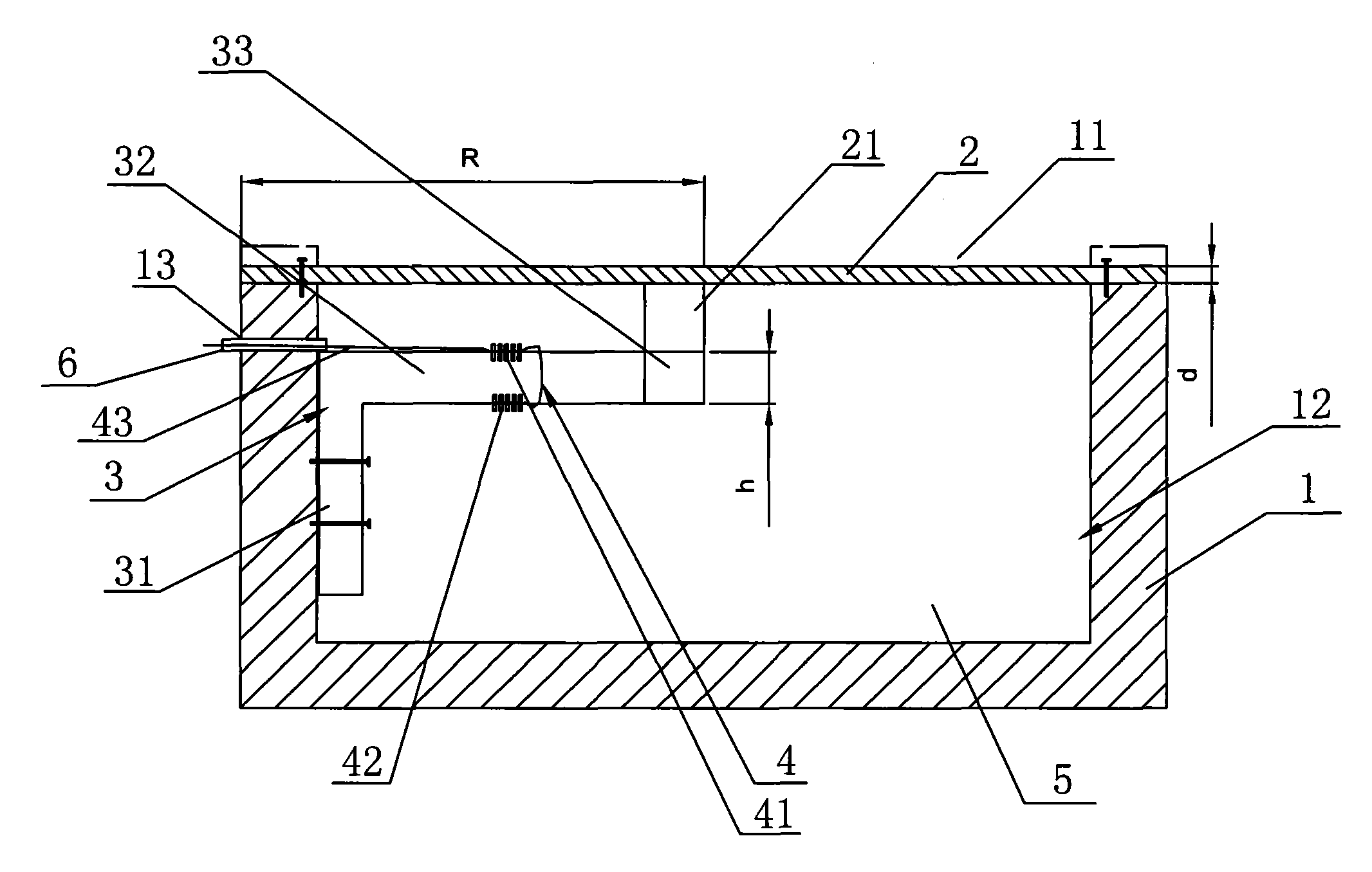
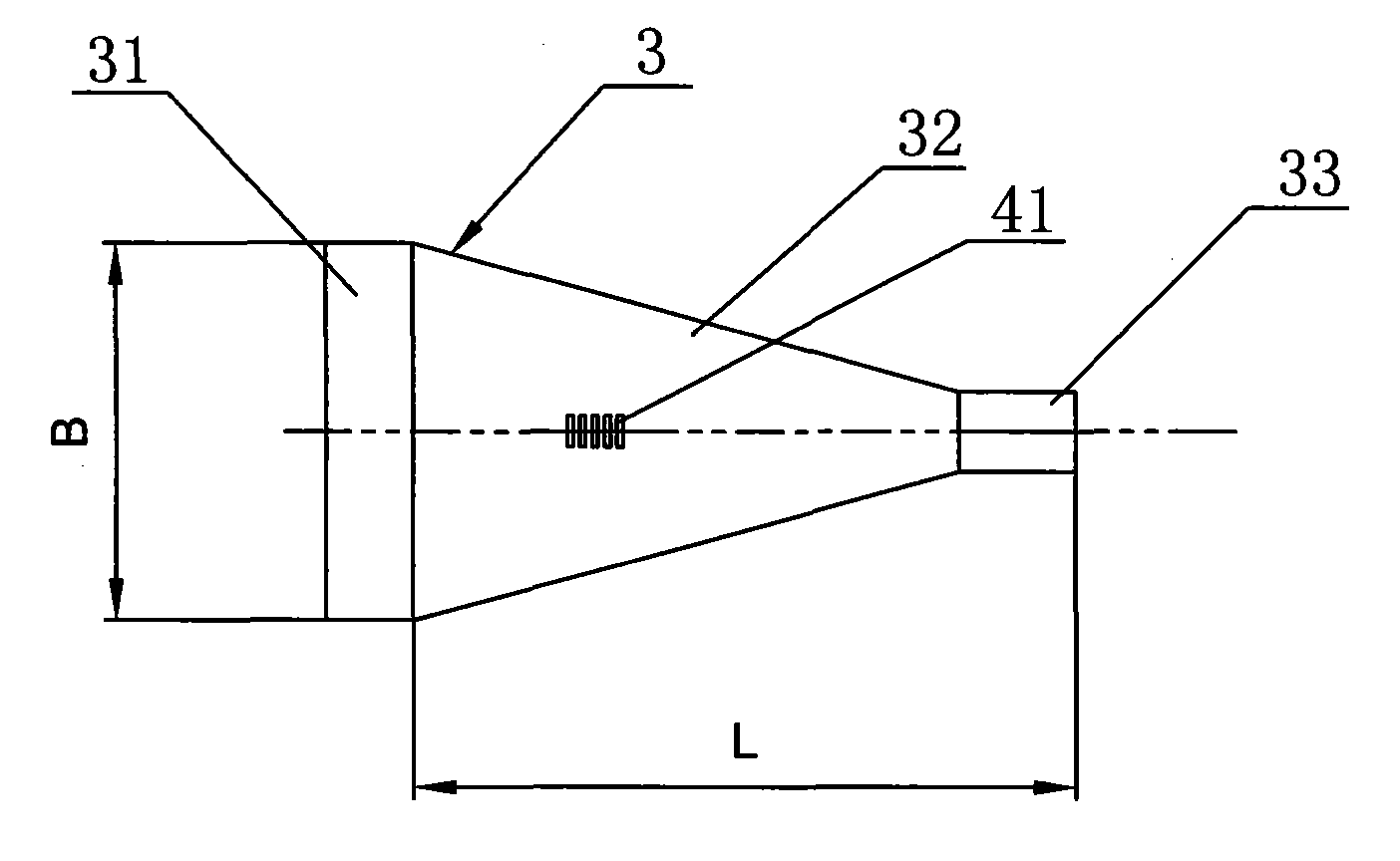
[0033] A kind of fiber Bragg grating pressure sensor that the present invention proposes, such as figure 1 and figure 2As shown, it includes a cylindrical housing 1, a circular elastic diaphragm 2, an L-shaped equal-intensity beam 3 and a fiber Bragg grating 4. An opening 11 is arranged on the top of the housing 1, and the opening 11 is connected to the housing. The internal space of 1 is connected to form a cavity 12 with an opening, the elastic diaphragm 2 is connected to the top of the housing 1, the elastic diaphragm 2 covers the opening 11, and the L-shaped equal-strength beam 3 is arranged in the cavity 12, L The fixed plate 31 of the equal-strength beam 3 can be fixedly connected with the cavity wall of the cavity 12 by fasteners such as screws, and the free end of the beam arm 32 of the L-shaped equal-strength beam 3 is provided with...


PUM


Abstract

The invention discloses an optical fiber Bragg grating pressure sensor and a corresponding measurement method thereof, and the sensor comprises a housing, an elastic diaphragm, an L-shaped uniform strength beam and an optical fiber Bragg grating, wherein an opening is arranged at the top end of the housing, the opening and internal space of the housing constitute a cavity body, the elastic diaphragm covers the opening, the uniform strength beam is arranged in the cavity body, a pressure block is arranged at the free end of a beam arm of the uniform strength beam, a hard boss which is tightly connected with the pressure block is arranged on the lower surface of the elastic diaphragm, the optical fiber Bragg grating is mainly constituted by connecting two Bragg gratings with the identical temperature gradient in series through an optical fiber, and the two Bragg gratings are respectively connected on the upper surface and the lower surface of the beam arm. The sensor has the advantages that the elastic diaphragm is in rigid connection with the beam arm during the design, thereby not only improving the measurement precision, but also reducing the process difficulty; as the optical fiber Bragg grating is mainly constituted by the two Bragg gratings with the identical temperature gradient, the sensor can solve the temperature cross sensitivity problem during the measurement.

Description

technical field [0001] The invention relates to an optical fiber sensor technology, in particular to an optical fiber Bragg grating pressure sensor and a corresponding measurement method thereof. Background technique [0002] Compared with conventional sensors, optical fiber sensors have obvious advantages in terms of sensitivity, dynamic range, and reliability, and are particularly prominent in construction, petroleum, and military applications. [0003] In the measurement of fiber optic sensors, in order to improve the accuracy and stability of the measurement, it is required to select appropriate sensitive components and package them reasonably. Good sensitive components, which are more and more concerned by people, have important application value in the fields of building monitoring, oil exploration and so on. Compared with conventional sensors, fiber Bragg grating sensors have higher sensitivity to physical quantities such as strain, temperature, and displacement, and...

Claims


Application Information

Patent Timeline
IPC IPC(8): G01L1/24G01L11/02
Inventor 李宏伟冷志鹏马佑桥
Owner NINGBO SHANGONG CENT OF STRUCTURAL MONITORING &CONTROL ENG
Learn More