
Double-ended exhaust head used for energy-saving lamp round exhaust

A technology of round row cars and energy-saving lamps, which is applied in the direction of electric tube/lamp exhaust, etc., can solve the problems of high vacuum system requirements, exhaustion of residual gas, and influence on pumping rate, etc., to reduce production costs and shorten exhaust Time, the effect of improving inner quality

Inactive Publication Date: 2012-05-23
XINXIANG K W L ELECTRICAL CO LTD
View PDF1 Cites 0 Cited by
  • Summary
  • Abstract
  • Description
  • Claims
  • Application Information

AI Technical Summary

Problems solved by technology

Due to the shape and sealing requirements of energy-saving lamps, the inner diameter of the glass rod is usually small, which greatly affects the pumping rate
Affected by this, the single-ended exhaust head has the following disadvantages: 1. The residual gas cannot be exhausted; 2. The argon flushing effect is poor; 3. The requirements for the vacuum system and the pump are high
However, since the two exhaust through holes share the same inner cavity, during the exhaust process, the two exhaust through holes are evacuated together and filled with argon, so that the airflow direction of the glass rod is the same, so in practice During the process, it is difficult to completely exhaust the impurity gas in the lamp tube. After the argon gas is filled, the impurity gas will still remain in the lamp tube, which has a great impact on the life of the lamp tube.

Method used


Image

  • Double-ended exhaust head used for energy-saving lamp round exhaust
  • Double-ended exhaust head used for energy-saving lamp round exhaust

Examples


Embodiment

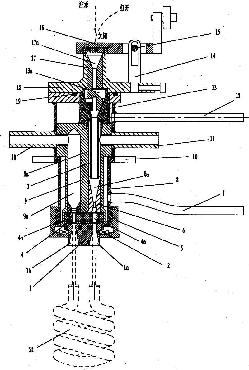
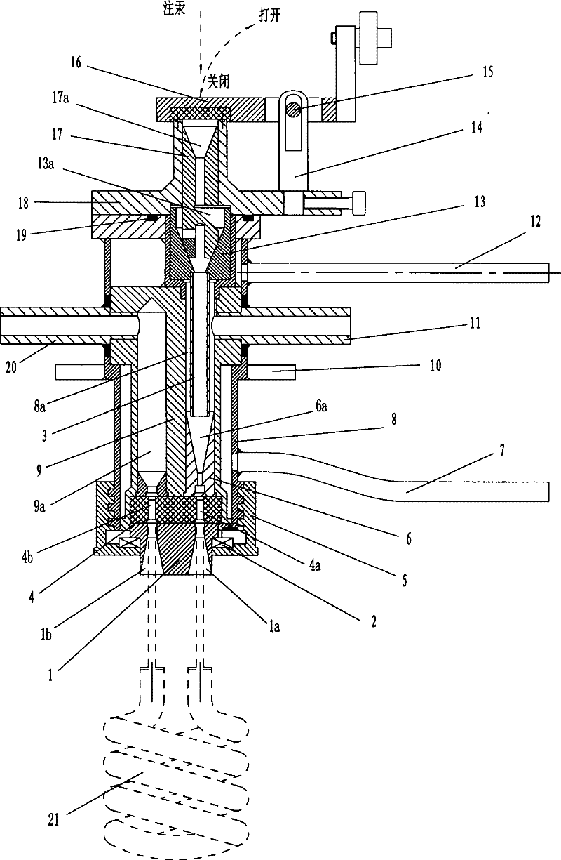
[0011] see figure 1 , the embodiment of the present invention includes a guide sleeve 1, a thrust bearing 2, a dropper 3, a clamping sleeve 4, a compression nut 5, a lower taper sleeve 6, a water inlet pipe 7, a casing 8, a body 9, a fixing plate 10, and a vacuum tube No. 1 11. Outlet pipe 12, upper taper sleeve 13, pillar 14, shaft 15, gland 16, soft iron bucket 17, bucket cover 18, sealing ring 19, No. 2 vacuum tube 20.

[0012] Mercury drop seat is contained in shell 8 upper ends, and it comprises bucket cover 18, pillar 14, gland 16, soft iron bucket 17 and upper taper sleeve 13.

[0013] The bucket cover 18 is fixed on the upper end of the shell 8, and a sealing ring 19 is fixed between the bucket cover 18 and the shell 8 in order to increase the sealing performance. The shell 8 has an inner cavity 8a, which extends from the lower end of the shell 8 to the bucket cover 18, and runs through the bucket cover 18, forming an inlet on the bucket cover 18. The pillar 14 is fi...


PUM


Abstract

The invention relates to a double-ended exhaust head used for an energy-saving lamp round exhaust, comprising an shell, a mercury-dripping base and a seal joint, wherein the seal joint is arranged at the lower end of the shell and comprises a lower taper sleeve, a clamping sleeve and a guide sleeve which are sequentially connected in serials; the lower taper sleeve is arranged at the lower end ofan inner cavity and is provided with a lower taper sleeve through hole communicated with the inner cavity; the clamping sleeve is provided with a clamping sleeve through hole 1 and a clamping sleeve through hole 2; the guide sleeve is provided with a guide sleeve through hole 1 and a guide sleeve through hole 2; the clamping sleeve through hole 1 is respectively communicated with the guide sleevethrough hole 1 and the lower taper sleeve through hole, and the clamping sleeve through hole 2 is communicated with the guide sleeve through hole 2; the lower end of the shell is in threaded connection with a gland nut which props against the guide sleeve upwards; and the side face of the shell is fixed with a vacuum tube 1 communicated with the inner cavity. The double-ended exhaust head is characterized by also comprising a vacuum tube 2 and a body which are fixed on the shell, wherein the body is provided with a body through hole; and one end of the body through hole is communicated with the vacuum tube 2, and the other end of the body through hole is communicated with the clamping sleeve through hole 2. The invention has reasonable structural design and good exhaust effect.

Description

technical field [0001] The invention relates to a double-end exhaust head for an energy-saving lamp round row car. Background technique [0002] The exhaust head installed on the energy-saving lamp round row car is mainly responsible for the processing tasks of energy-saving lamp exhaust and mercury drop. Exhaust heads used for energy-saving lamp exhaust machines in the prior art are generally single-ended exhaust. During processing, first seal one of the two glass rods with fire, then connect the exhaust head to the other glass rod, first vacuumize, then drop mercury, and finally fire to seal. Due to the shape and sealing requirements of energy-saving lamps, the inner diameter of the glass rod is usually small, which greatly affects the pumping rate. Affected by this, the single-ended exhaust head has the following disadvantages: 1. The residual gas cannot be exhausted; 2. The argon flushing effect is poor; 3. The requirements for the vacuum system and the pump are high. ...

Claims


Application Information

Patent Timeline
Patent Type & Authority Patents(China)
IPC IPC(8): H01J9/385
Inventor 张高起翁志荣
Owner XINXIANG K W L ELECTRICAL CO LTD
Learn More