
Floor non-contact power supply device of lift car

An elevator car, non-contact technology, applied in the direction of circuit devices, electrical components, electromagnetic wave systems, etc., can solve problems such as easy fires, and achieve the effects of avoiding eddy current heating and fire hazards, and avoiding conductor breakage and insulation aging

Inactive Publication Date: 2013-10-30
SUZHOU KANGKAI ELECTRIC +1
View PDF1 Cites 0 Cited by
  • Summary
  • Abstract
  • Description
  • Claims
  • Application Information

AI Technical Summary

Problems solved by technology

However, in this form of non-contact power supply, since the feeder 34 that flows through the high-frequency current is exposed to the magnetic field in the entire elevator shaft, the electromagnetic compatibility problem caused by it cannot be ignored.
On the other hand, if there is a metal object (such as a wrench or the like) close to the feeder 34 exposed to the magnetic field, the resulting eddy (electric) current is very likely to cause a fire

Method used


Image

  • Floor non-contact power supply device of lift car
  • Floor non-contact power supply device of lift car
  • Floor non-contact power supply device of lift car

Examples


Embodiment approach 1

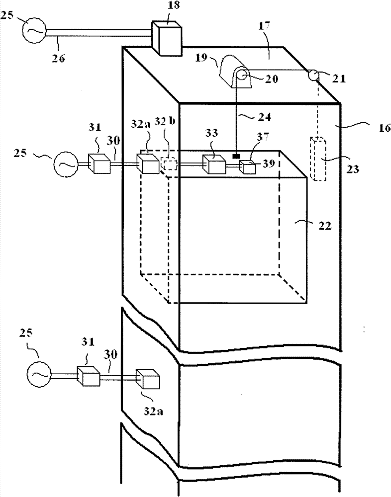
[0027] figure 1 It is a schematic diagram of main parts of Embodiment 1 of the floor-by-floor non-contact power supply device for elevator cars of the present invention.

[0028] The top 17 of the elevator hoistway 16 in buildings such as buildings is equipped with control cabinet 18 and winch 19; On the main pulley 20 and secondary pulley 21 of winch 19, hang with main wire rope 24, and one end of main wire rope 24 is the elevator car The other end of 22 is a counterweight 23; the three-phase industrial frequency power supply 25 supplies electric energy to the control cabinet 18 through the power transmission cable 26; The operation specified for the destination station shows the centralized control system. This is the driving signal of the elevator car.

[0029] The invention solves the non-contact power supply of the load in the car by floor, figure 1 The middle feeding part 31 is connected between the commercial frequency power supply 25 and the detachable electromagnet...

Embodiment approach 2

[0034] Fig. 5 is a schematic diagram of main parts of an elevator system of an elevator car floor-by-floor non-contact power supply device according to Embodiment 2 of the present invention. and figure 1 In the elevator car according to Embodiment 1 shown, the parts that are the same as the non-contact power supply devices for each floor are denoted by the same reference numerals, and descriptions of overlapping parts are omitted. In addition, other parts because of the Figure 2 to Figure 4 The same, so its description is also omitted.

[0035] In the floor-by-floor non-contact power supply device for elevator cars in Embodiment 2, there may be only one power feeding part 31 in the whole device, and the detachable electromagnetic mechanisms on all floors are fed by it in time division. Like this, because the distance from the feeder part 31 to the separable electromagnetic mechanism 32 of each floor is inconsistent, the connecting line has an inconsistent inductance (the lo...


PUM


Abstract

The invention discloses a floor non-contact power supply device of a lift car. A power feeding part is installed on each floor through which a lift car passes while lifting; a power receiving part corresponding to the power feeding part at each floor is installed on the lift car; the power feeding part and the power receiving part transmit power by a non-contact inductive coupling separable electromagnetic mechanism when the lift car is level and static; the power receiving part uses the power obtained by inductive coupling for the drive of a load in the lift car and the energy storage of a storage battery; by discarding a cable suspending lift car power supply way, the defects of breaking and insulation aging of a conductor of a cable can be overcome; and by adopting the floor non-contact power supply way, the problem in the aspect of electromagnetic compatibility caused by exposing a high-frequency guide rail magnetic field and expected eddy current heating and a fire hazard brought by metal can be avoided.

Description

technical field [0001] The present invention relates to a power supply device for an elevator or a similar elevator system, in particular to a floor-by-floor non-contact power supply device for an elevator car that supplies power to the car when the leveling floor is stationary from the outside of the elevator car in a non-contact manner. Background technique [0002] An elevator or elevator system has a box-shaped space, called a car, that moves up and down in the hoistway (shaft) to carry passengers or other loads. As shown in Figure 6, the AC power supply 25 supplies power to the elevator control cabinet 18 and the electrical box 27 through the transmission line 26, and the car 22 is located in the hoistway 16 and moves up and down under the action of the hoist mechanism. The conventional power supply mode of the elevator car is completed by a bundle of cables 38 suspended in the elevator shaft 16. This bundle of cables expands and contracts within a certain range with th...

Claims


Application Information

Patent Timeline
Patent Type & Authority Patents(China)
IPC IPC(8): H02J17/00H02J50/12
Inventor 潘文诚沈永福
Owner SUZHOU KANGKAI ELECTRIC
Learn More