Motor, fan and stator device thereof

A technology for motors and stators, applied to pump devices, electromechanical devices, casings/covers/supports, etc., can solve the problem that the rotation stability of the rotor 92 cannot be further improved, the rotation stability of the rotor 92 is not good, and it is difficult to master the motor assembly Quality and other issues, to achieve the effect of improving the convenience of assembly, improving the stability of rotation, and preventing the leakage of lubricating oil

Inactive Publication Date: 2010-12-01
SUNONWEALTH ELECTRIC MACHINE IND
View PDF0 Cites 13 Cited by
  • Summary
  • Abstract
  • Description
  • Claims
  • Application Information

AI Technical Summary

Problems solved by technology

However, since the bottom of the rotating shaft 921 of the existing motor must reserve a length (L) in advance, the locking groove 922 can be formed for engaging the buckle ring 94, therefore, the rotating shaft 921 is close to the outer peripheral surface of the bottom It cannot be rotatably combined with the bearing 96. In other words, since the bottom of the rotating shaft 921 has the locking groove 922, the combined area between the rotating shaft 921 and the bearing 96 will be further limited, causing the rotor The rotation stability of 92 cannot be further improved, especially for micro-miniature existing motors, under the condition that the combined area between the rotating shaft 921 and the bearing 9...

Method used


Image

  • Motor, fan and stator device thereof
  • Motor, fan and stator device thereof
  • Motor, fan and stator device thereof

Examples


Embodiment Construction

[0038] In order to make the above and other objects, features and advantages of the present invention more comprehensible, the preferred embodiments of the present invention are specifically cited below, together with the accompanying drawings, as follows:

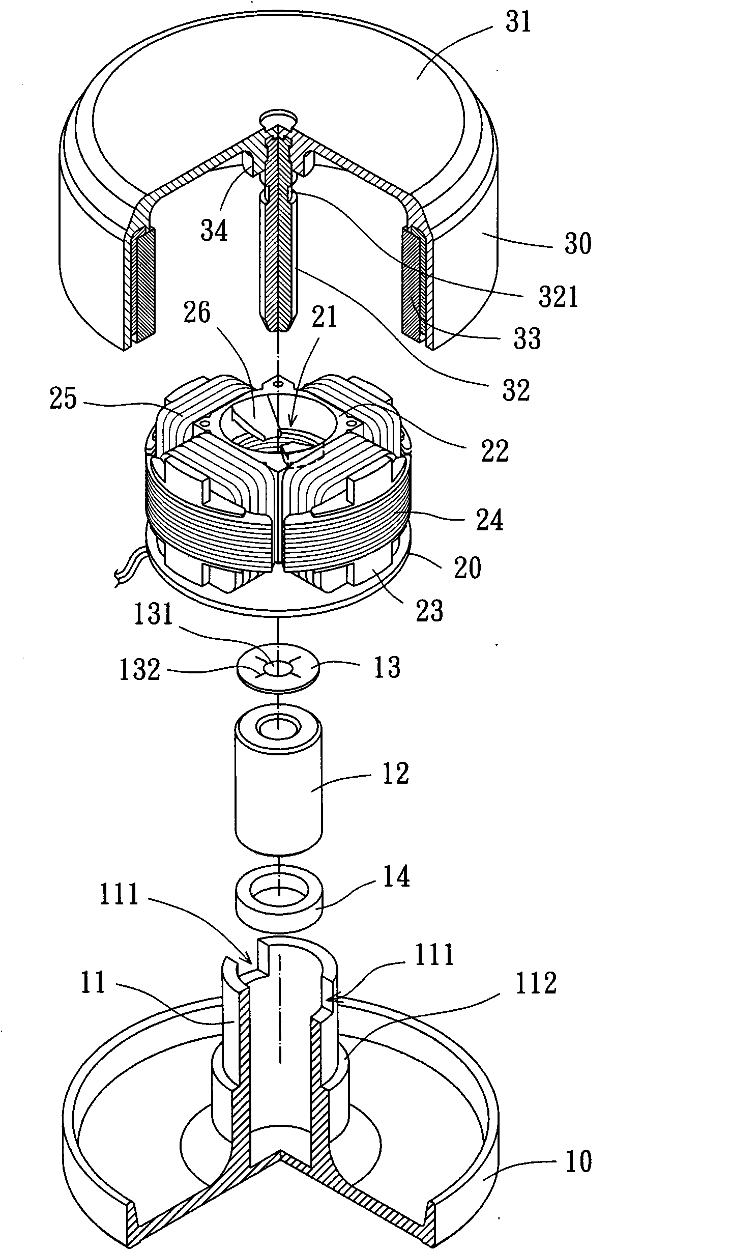
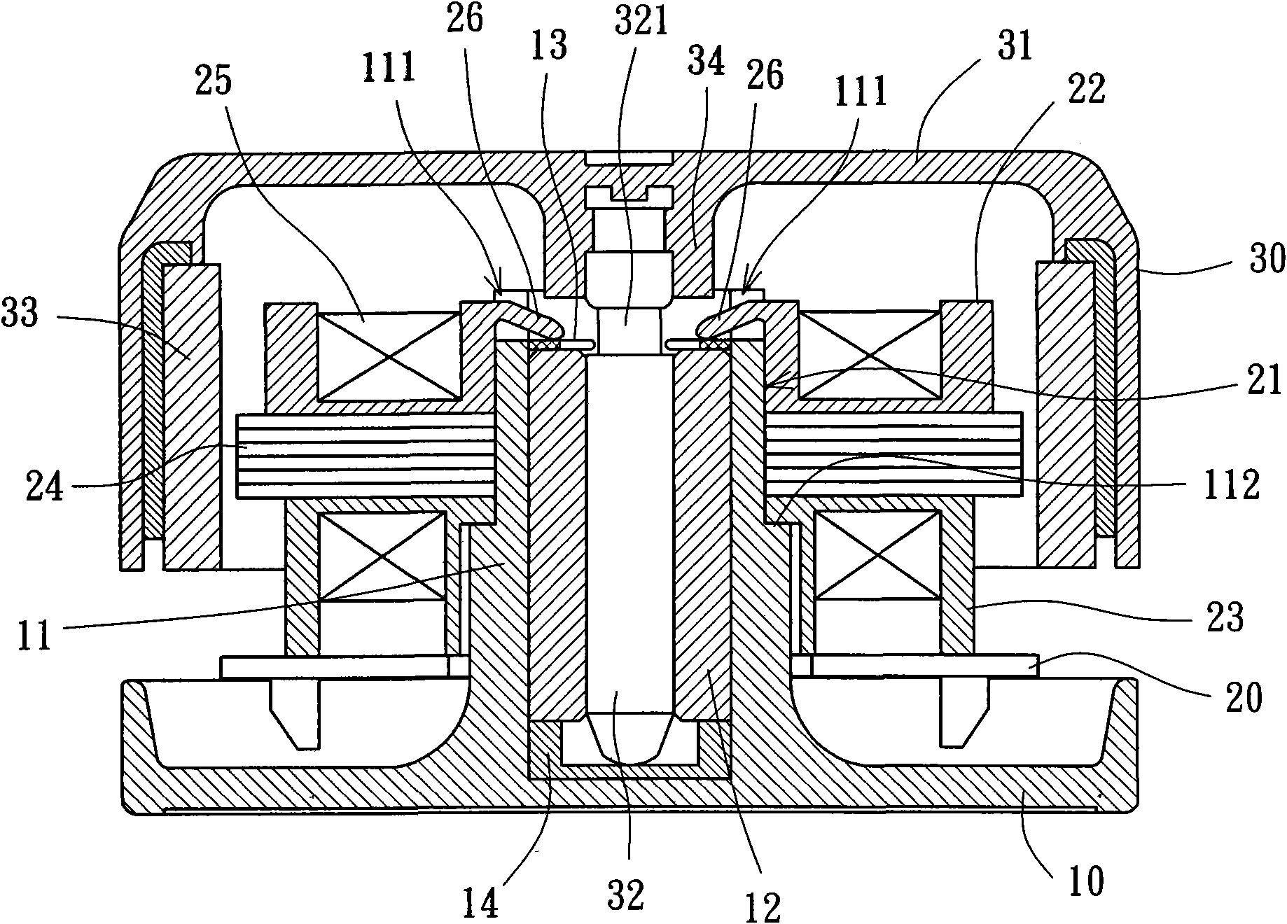
[0039] Please refer to figure 2 and 3 As shown, the motor of the first embodiment of the present invention mainly includes a stator device and a rotor, wherein the stator device includes a casing 10 and a stator assembly 20, and the rotor 30 can be pivotally connected to the stator device for rotation . in:

[0040] A shaft tube 11 is provided in the center of the shell base 10, and the bottom of the shaft tube 11 is preferably closed, and a bearing 12, an abutment plate 13, a supporting member 14 and other components can be placed in the shaft tube 11 .

[0041]The top of the shaft tube 11 is provided with at least one groove 111. In this embodiment, the top of the shaft tube 11 is provided with two grooves 111. The ...


PUM


Abstract

The invention relates to a motor and a stator device thereof, wherein the stator device comprises a shell base and a stator group; the center of the shell base is provided with a shaft tube which is internally provided with a bearing; the top end of the shaft tube is provided with as least one groove; the stator group is provided with an assembling hole which penetrates the stator group throughlyin the axial direction; the assembling hole is sleeved at the outer peripheral surface of the shaft tube, and the stator group is provided with at least one stopper which passes through the groove ofthe shaft tube and protrudes at the inner side of the shaft tube so as to restrict the bearing from loosening; and the center of the stator is provided with a rotary shaft which is pivoted on the bearing, thereby effectively improving the assembly convenience and rotation reliability of the motor and the stator device thereof. The invention is named as motor, fan and stator device thereof.

Description

technical field [0001] The invention relates to a motor, a fan and a stator device thereof, in particular to a motor, a fan and a stator device thereof which can be easily assembled. Background technique [0002] Please refer to figure 1 As shown, the conventional motor 9 includes a casing 91 , a rotor 92 and a stator assembly 93 . There is a hollow shaft tube 911 in the center of the shell base 91, and components such as a bearing 96, a retaining ring 94, and an oil storage cylinder 95 can be placed inside the shaft tube 911; the rotor 92 has a rotating shaft 921 in the center, and the rotating The shaft 921 is rotatably pivotally connected to the bearing 96, and a locking groove 922 is formed on the outer peripheral surface of the rotating shaft 921, and the locking groove 922 is adjacent to the bottom of the rotating shaft 921, for the locking ring 94 to be engaged; The stator assembly 93 is installed on the outer peripheral surface of the shaft tube 911 to drive the ro...

Claims


Application Information

Patent Timeline
IPC IPC(8): H02K5/04H02K1/22F04D25/08
Inventor 洪银树
Owner SUNONWEALTH ELECTRIC MACHINE IND
Why Eureka
Try Eureka