Diffuser and manufacturing method thereof

A manufacturing method and a technology for a diffuser, which are applied in chemical instruments and methods, water aeration, sustainable biological treatment, etc., can solve the problems of reduced oxygen transmission efficiency, poor impact resistance and wear resistance, and short service life, and achieve Excellent durability, air tightness and air permeability, improved wear resistance and impact resistance, high oxygen transmission efficiency

Inactive Publication Date: 2010-12-08
GREEN TECH CO LTD
View PDF6 Cites 0 Cited by
  • Summary
  • Abstract
  • Description
  • Claims
  • Application Information

AI Technical Summary

Problems solved by technology

[0003] However, the membrane diffuser has a structure in which the stretchable membrane repeatedly expands and contracts, so the service life is short due to the fatigue load, and the soft EPDM membrane with poor impact resistance and wear resistance, when filled with the mobile phase carrier , easy to be worn or damaged when colliding with the flowing carrier
[0004] In addition, in the rod-type diaphragm air diffuser, since the air bubbles also float up from the bottom of the rod along the surface of the rod, the frequency of the collision of the air bubbles increases, and the air bubbles will merge into large air bubbles after the collision with each other, so the oxygen transmission will be reduced efficiency
[0005] In addition, in the disc-type membrane diffuser, the oxygen transfer efficiency is high because the air bubbles will not merge. However, when the EPDM disc is placed on the disc-type substrate and fixed with a peripheral frame, the peripheral frame and the lower substrate need to be fixed with screws. Or use bolts and nuts to assemble, so there is a problem that the screw connection part is loose or the connection part of the bolt and nut is not firm
[0006] In addition, the air diffuser of the diaphragm may also be blocked due to the adhesion of biofilm. When the air diffuser is blocked, it needs to be regularly removed with formic acid, so it is troublesome to manage.

Method used


Image

  • Diffuser and manufacturing method thereof
  • Diffuser and manufacturing method thereof
  • Diffuser and manufacturing method thereof

Examples


Embodiment Construction

[0031] Preferred embodiments of the present invention will be described in detail below with reference to the accompanying drawings.

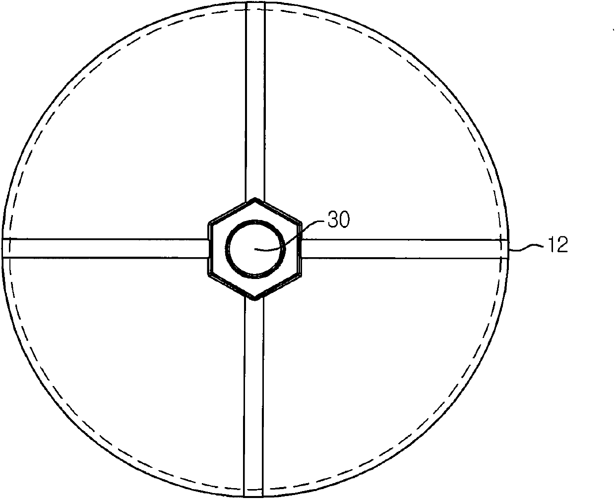
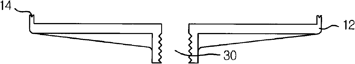
[0032] Figure 1a It is a longitudinal sectional view of the upper body 11 with a plurality of diffuser openings 20; Figure 1b It is a longitudinal cross-sectional view of the lower body 12 having the air supply port 30 .

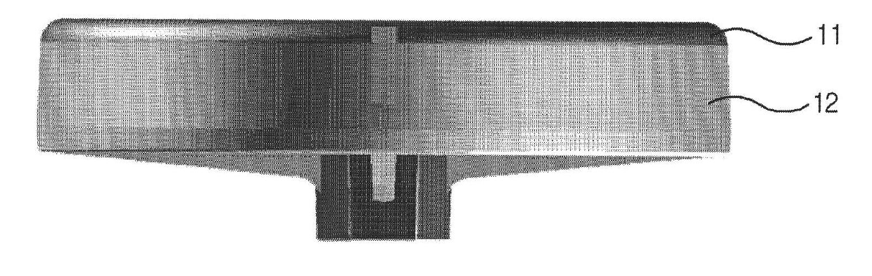
[0033] The above-mentioned main bodies 11, 12 formed by the above-mentioned upper main body and the lower main body are welded to each other at the joint part 14, and after being combined into one main body, the structure is as follows: image 3 As shown in the air diffuser 1 , a space 13 through which air can circulate is formed inside the air diffuser 1 .

[0034] Wherein, the above-mentioned diffuser pipe 1 can be combined by thermal welding, that is, the joint parts of the main bodies 11 and 12 made of thermoplastic synthetic resin are heated with an electric heating plate, and the surfaces are melted and then crimped ...


PUM


Abstract

The invention relates to a diffuser and a manufacturing method thereof, in particular to a device for supplying dissolved oxygen to reaction slots in wastewater treatment facilities, oceans, rivers and plants for culturing aerobic microorganism, improving the water system self-purification capacity and cultivate fishes at a high density. The apparatus can disperse air transferred from a blower into fine bubbles, thereby increasing dissolved oxygen in water. The diffuser includes a plurality diffusion holes capable of generating fine bubbles and one or more air supply ports capable of receiving air from the blower. The diffuser is formed by more than two main bodies produced by thermoplastic synthetic resin molded small bonded by fusion and can maintain a stable oxygen delivering efficiency; and the combination portion on the diffuser is excellent in airtightness.

Description

technical field [0001] The present invention relates to an air diffuser and a manufacturing method thereof, in particular to supplying oxygen to reaction tanks, lakes, rivers, farms, etc. The device can disperse the air provided by the blower into fine bubbles in the water, thereby increasing the amount of dissolved oxygen. Background technique [0002] There are many kinds of existing diffuser tubes (Diffuser), which have various shapes and structures, and are made of various materials. Among them, the membrane (Membrane) diffuser tube formed by perforating fine diffuser holes on the soft membrane has the highest oxygen transfer efficiency. [0003] However, the membrane diffuser has a structure in which the stretchable membrane repeatedly expands and contracts, so the service life is short due to the fatigue load, and the soft EPDM membrane with poor impact resistance and wear resistance, when filled with the mobile phase carrier , It is easy to be worn or damaged when i...

Claims


Application Information

Patent Timeline
IPC IPC(8): C02F7/00C02F3/02B29C65/02
CPCY02W10/10C02F3/20C02F2201/002
Inventor 韩相培
Owner GREEN TECH CO LTD
Why Eureka
Try Eureka