Hot-blast stove of biomass energy source

A biomass energy, hot blast stove technology, applied in air heaters, fluid heaters, lighting and heating equipment, etc., can solve problems such as being unsuitable for use in rural fields, complex structure, etc., and achieve high thermal utilization value and wide application range. , the effect of easy relocation

Inactive Publication Date: 2010-12-08
SICHUAN HUINONG MACHINERY
7 Cites 27 Cited by

AI-Extracted Technical Summary

Problems solved by technology

Although the hot air generating device is feasible, its structur...

Abstract

The invention discloses a hot-blast stove of a biomass energy source, comprising a flame bridge, a stove door, a shell, a smoke outlet, a feeding door, a burning bin and a fuel bin. The hot-blast stove of the biomass energy source is characterized in the shell is internally provided with a liner; the liner is internally provided with the flame bridge, the fuel bin, the burning bin, a heat transfer device and the smoke outlet from bottom to top; the lower part of the shell is provided with a cold air inlet; the outlet of a blower is connected with a cold air inlet; the inner wall of the shell and the outer wall of the liner form a cold air cavity; the inner wall of the liner and the outer walls of the heat transfer device, the burning bin and the fuel bin form a hot air cavity; an air inlet of the liner is arranged on the wall of the upper part of the liner, and a hot air outlet is arranged on the wall of the lower part of the liner; and the burning bin is provided with a feeding port, and the feeding door is arranged at the feeding port. The hot-blast stove has the advantages of scientific, reasonable, smart and flexible structure, convenient moving and higher heat utilization rate; the hot-blast stove is particularly suitable for roasting foxtail millet, maize and wheat in village by using the high-temperature hot air, has no mildewing and is economic and environment-friendly, thereby having promotional value.

Application Domain

Technology Topic

Image

  • Hot-blast stove of biomass energy source
  • Hot-blast stove of biomass energy source
  • Hot-blast stove of biomass energy source

Examples

  • Experimental program(1)

Example Embodiment

[0019] Example
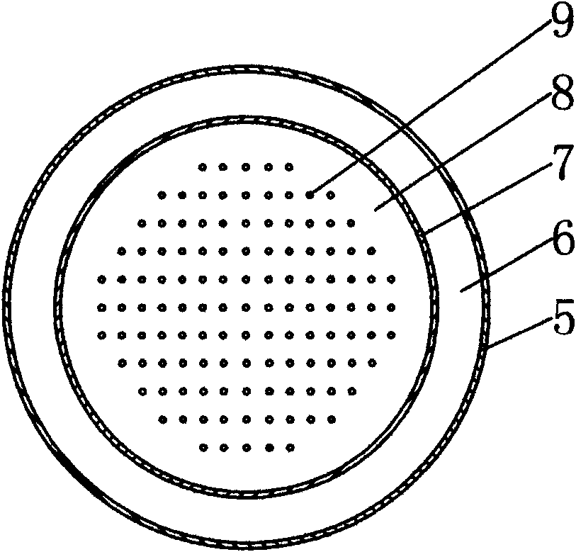
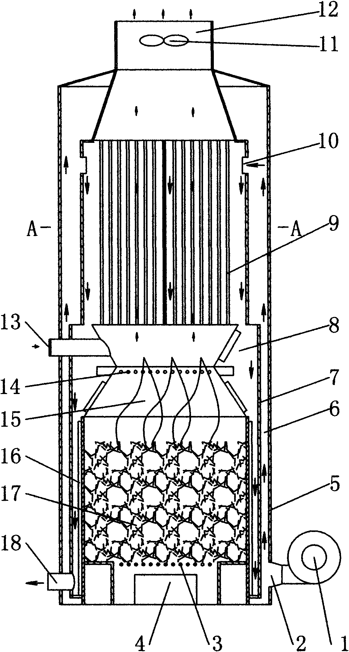
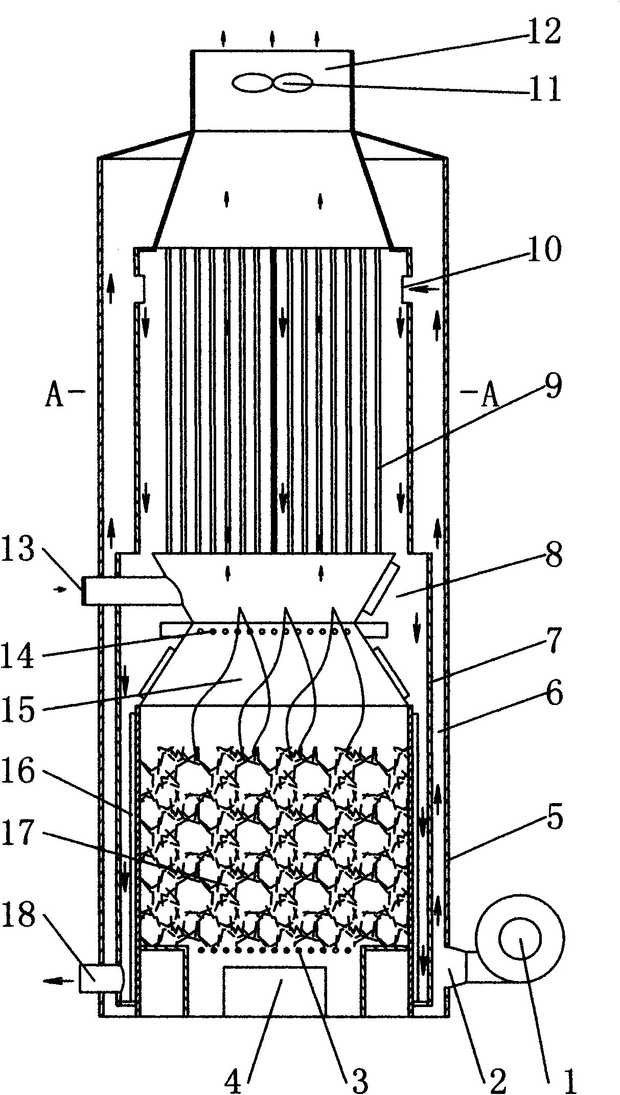
[0020] A biomass energy hot blast stove, comprising a furnace bridge 3, a furnace door 4, a shell 5, a smoke outlet 12, a feed door 13, a combustion bin 15, a fuel bin 17, an inner bladder 7 is arranged in the shell 5, The inner tank 7 is provided with a furnace bridge 3, a fuel tank 17, a combustion tank 15, a heat conductor 9, and a smoke exhaust port 12 from bottom to top; the lower part of the shell 5 is provided with a cold air inlet 2, an outlet of the blower 1 and a cold air inlet 2 is connected; the inner wall of the outer shell 5 and the outer wall of the inner liner 7 form a cold air cavity 6; the inner wall of the inner liner 7 forms a hot air cavity 8 with the outer walls of the heat conductor 9, the combustion chamber 15, and the fuel chamber 17; the upper wall of the inner liner 7 The inner tank air inlet 10 is provided on the upper part, the hot air outlet 18 is provided on the lower wall of the inner tank 7; the combustion chamber 15 is provided with a feed port, and the feed port is provided with a feed door 13, which requires heating The cold air is first sent into the cold air chamber 6 by the blower 1 from the cold air inlet 2 and the air is gradually preheated from bottom to top. Secondly, the preheated air enters the hot air chamber 8 from the air inlet 10 of the inner tank, and the air flows from top to bottom. It is gradually heated, and the heated air is discharged from the hot air outlet 18. The blower 1 is preferably a high-pressure blower. The heat conductor 9 is composed of a plurality of heat conduction pipes arranged vertically. The lower end of the heat conduction pipe is connected with the upper part of the combustion chamber 15 and the top of the heat conduction pipe communicates with the exhaust port 12. An oxygen supply 14 is provided in the middle of the combustion chamber 15. The structure of the oxygen supply 14 is a small through hole in the middle wall of the combustion chamber 15. The oxygen supply 14 sends a small amount of hot air from the hot air cavity 8 into the combustion chamber 15 Combustion. An exhaust fan 11 is provided at the exhaust port 12. Heat transfer fins 16 are provided on the outer walls of the combustion bin 15 and the fuel bin 17. Adjusting the inlet air size of the furnace door 4 or the feed door 13 controls the temperature of the hot air discharged from the hot air outlet 18. A temperature display sensor can be installed at the hot air outlet 18. The biomass energy hot air stove of the present invention needs to be matched with a corresponding drying device when used. The biomass energy hot air stove and drying device can also be installed in rural fields or yard dams or small cars to dry millet, corn, wheat and other crop products on site.

PUM

no PUM

Description & Claims & Application Information

We can also present the details of the Description, Claims and Application information to help users get a comprehensive understanding of the technical details of the patent, such as background art, summary of invention, brief description of drawings, description of embodiments, and other original content. On the other hand, users can also determine the specific scope of protection of the technology through the list of claims; as well as understand the changes in the life cycle of the technology with the presentation of the patent timeline. Login to view more.

Similar technology patents

Unmanned remote maintenance system for elevator

InactiveCN108706416AStructural scienceElevatorsPower sensorEngineering
Owner:湖北天禾立方智能科技发展有限公司

Classification and recommendation of technical efficacy words

  • Structural science
  • Easy to move

Extruding-punching forging die for hub unit

InactiveCN106984755AStructural scienceReduce mold usageForging/hammering/pressing machinesWheelsForgingMetal flow
Owner:HUBEI TRI RING FORGING

Container base structure responsive to vacuum related forces

ActiveUS20090159556A1Restrain all pressure and forceEasy to moveLarge containersRigid containersVacuum pressure
Owner:AMCOR RIGID PLASICS USA LLC
Why Eureka
Try Eureka