Double-liquid capillary micro-flow control valve in micro-flow control chip, and manufacturing method thereof

A technology of a microfluidic chip and a manufacturing method, which are applied in the photoengraving process, valve device, instrument and other directions of the pattern surface, can solve the problem of difficulty in achieving high affinity for liquid while injecting the liquid residue, increasing the complexity of the process and the difficulty of processing, High liquid affinity is easy to fail, etc., to achieve the effects of cheap structural materials, improved reliability, and guaranteed simultaneity

Inactive Publication Date: 2010-12-08
CHANGCHUN INST OF OPTICS FINE MECHANICS & PHYSICS CHINESE ACAD OF SCI
View PDF7 Cites 16 Cited by
  • Summary
  • Abstract
  • Description
  • Claims
  • Application Information

AI Technical Summary

Problems solved by technology

The production of steam traps requires local surface treatment, which will increase the complexity and difficulty of the process, and the process compatibility is poor; the expansion valve mainly relies on the expansion of the size to achieve the cut-off of the flow, and it is easy to fail for highly hydrophilic liquids
Therefore, the usual Y-shaped sampling microchannel has the disadvantages of complex processing technology, poor process compatibility, difficulty in achieving simultaneous sampling with high affinity for liquids, and the existence of liquid residues.

Method used


Image

  • Double-liquid capillary micro-flow control valve in micro-flow control chip, and manufacturing method thereof
  • Double-liquid capillary micro-flow control valve in micro-flow control chip, and manufacturing method thereof
  • Double-liquid capillary micro-flow control valve in micro-flow control chip, and manufacturing method thereof

Examples


specific Embodiment approach 1

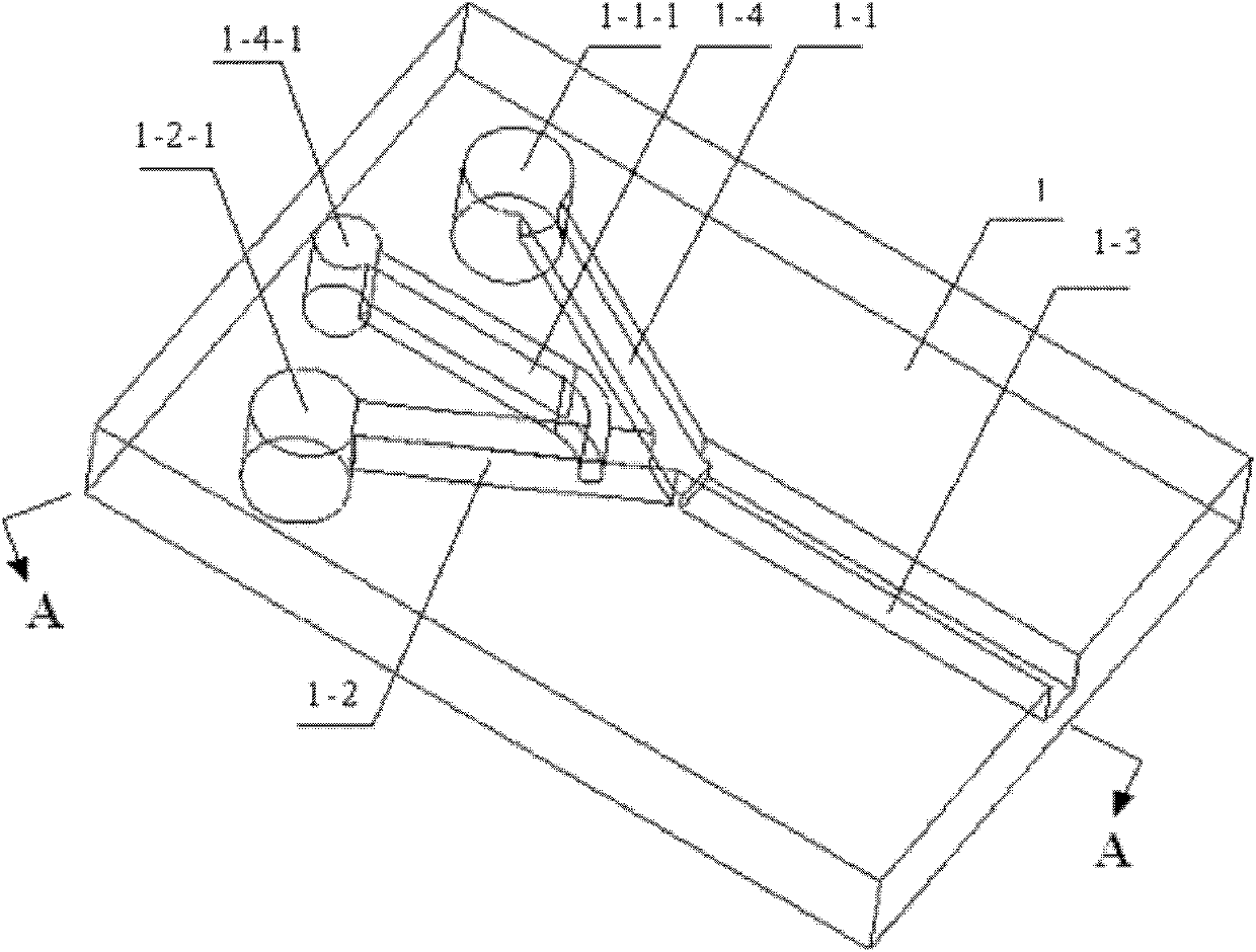
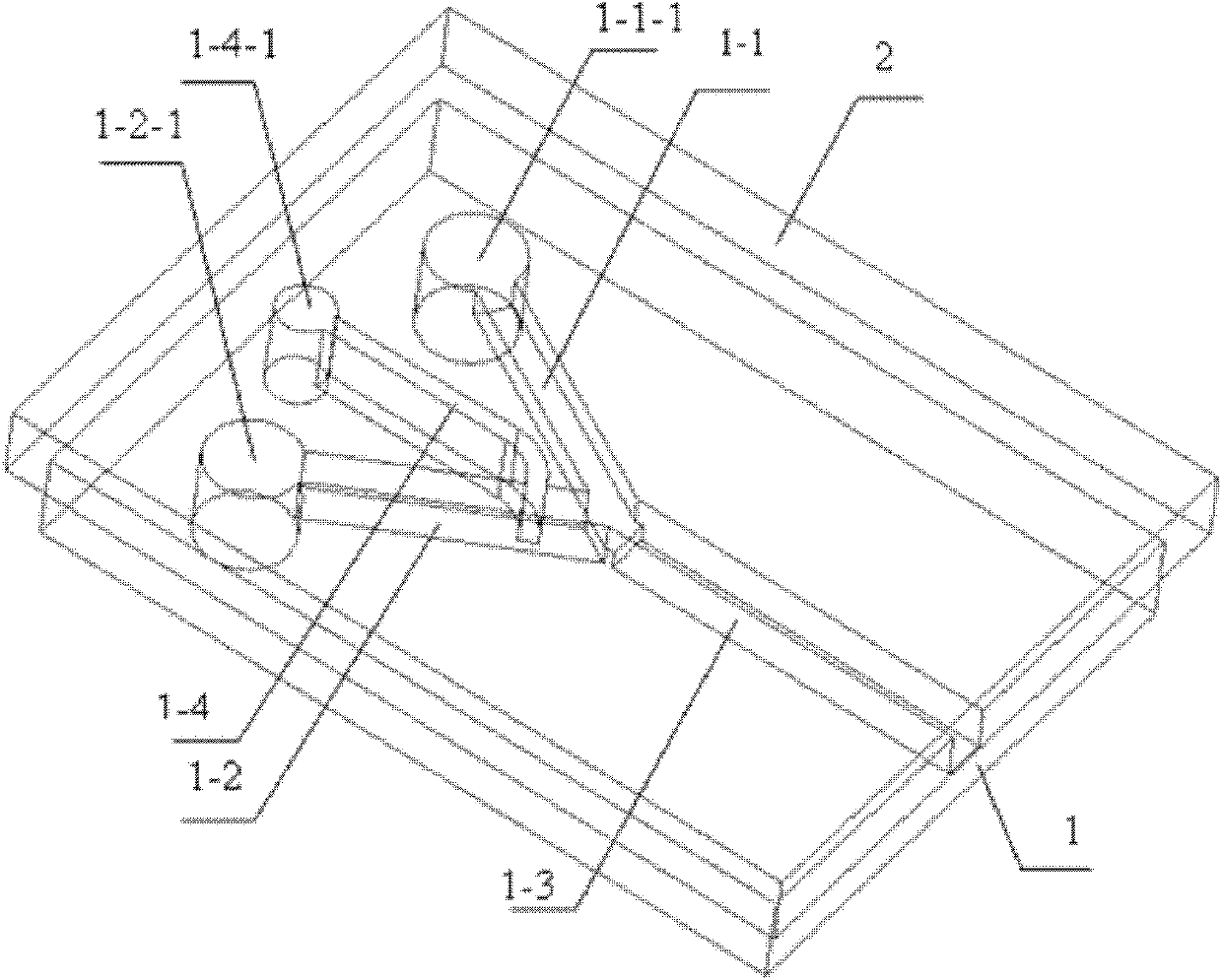
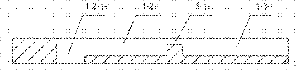
[0023] Specific implementation mode 1. Combination Figure 1 to Figure 3 To illustrate this embodiment, the dual-liquid capillary micro-flow control valve in the microfluidic chip is a Y-shaped capillary channel formed by placing the PDMS substrate 1 with grooves on the surface on the surface of the glass sheet 2. The grooves on the surface of the sheet 1 include a first tributary groove 1-1, a second tributary groove 1-2, an output groove 1-3 and an airway groove 1-4; the first tributary groove 1-1 1. The cross-sectional width of the second tributary groove 1-2 and the output groove 1-3 is equal; the cross-sectional width of the air channel groove 1-4 is smaller than the first tributary groove 1-1, the second tributary groove 1-2 and the cross-sectional width of the output groove 1-3; the depth of the second tributary groove 1-2 and the output groove 1-3 are equal, and the depth of the first tributary groove 1-1 is smaller than the second tributary groove The depth of the gr...

specific Embodiment approach 2

[0026] Embodiment 2. This embodiment is a method for manufacturing the dual-liquid capillary microfluidic control valve in the microfluidic chip described in Embodiment 1. The specific steps of the method are:

[0027] Step 1. Spin-coat photoresist on the surface of the oxidized Si single wafer, and photoetch the first tributary groove 1-1, the second tributary groove 1-2, the output groove 1-3 and the air channel The photoresist pattern of the grooves 1-4, and then wet-etch SiO after the photoresist pattern is hardened 2 , and then remove the photoresist of the first tributary groove 1-1, the second tributary groove 1-2, the output groove 1-3 and the remaining part of the airway groove 1-4 to obtain the first tributary groove 1- 1. SiO of the second tributary groove 1-2, the output groove 1-3 and the airway groove 1-4 channel 2 mask pattern;

[0028] Step 2, the SiO obtained in step 1 2Evaporate a 1 μm thick aluminum film on the mask pattern, then spin-coat photoresist on ...


PUM

PropertyMeasurementUnit
thicknessaaaaaaaaaa
depthaaaaaaaaaa
widthaaaaaaaaaa

Abstract

The invention relates to a double-liquid capillary micro-flow control valve in a micro-flow control chip, and a manufacturing method thereof, in particular to a capillary micro-flow control mechanism which is used for the micro-flow control chip and can realize sample injection of two liquids at the same time, aiming at solving the technical problem that the sample injection of the two trace liquids with different medium affinity properties can be difficultly realized in the existing micro-flow control technology. The double-liquid capillary micro-flow control valve is provided with a first branch flow groove, a second branch flow groove and an output groove which have equal cross section width; the cross section width of an air duct groove is less than that of the first branch flow groove, the second branch flow groove and the output groove; the depth of the second branch flow groove is equal to that of the output groove, and the depth of the first branch flow groove is less than that of the second branch flow groove; the depths of the second branch flow groove and the output groove are less than that of the air duct groove; the ends of the first branch flow groove and the second branch flow groove are communicated with an input end of the output groove; and the end of the air duct groove is communicated in front of the end of the second branch flow groove. The invention is applicable to the structure of a device which can lead the sample injection of high-affinity liquid to be carried out at the same time.

Description

technical field [0001] The invention relates to a capillary and micro-flow control valve for simultaneous sampling of two liquids on a microfluidic chip, in particular a control mechanism suitable for synchronous feeding of two trace liquids with different medial properties in biological detection . Background technique [0002] Microfluidic chips are currently a hot spot in the development of Miniaturized Total Analysis Systems. The microfluidic chip integrates the microstructure used to complete the processes of sample processing, transportation, quantification, mixing and detection on the chip, which constitutes the main platform for the realization of microfluidic technology. On the chip, the liquid mixing operation requires two liquids to enter the micro-mixer at the same time, and this function is completed by the Y-shaped sampling microchannel. Usually, the capillary flow of the two liquids in the Y-shaped sampling microchannel at the junction of the two sampling br...

Claims


Application Information

Patent Timeline
Patent Type & Authority Applications(China)
IPC IPC(8): G01N35/10G03F7/00F16K13/00
Inventor 邓永波吴一辉张平刘震宇刘永顺黎海文
Owner CHANGCHUN INST OF OPTICS FINE MECHANICS & PHYSICS CHINESE ACAD OF SCI
Why Eureka
Try Eureka