Infrared and glimmer multispectral fusion front end optical-mechanic structure

A pre-fusion, multi-spectral technology, applied in optics, optical components, instruments, etc., can solve the problems of optical signal attenuation, difficult transmittance, high parallel precision requirements, etc., to achieve convenient operation and use, avoid manufacturing process, and improve coincidence degree of effect

Inactive Publication Date: 2010-12-08
NANJING UNIV OF SCI & TECH
View PDF4 Cites 13 Cited by
  • Summary
  • Abstract
  • Description
  • Claims
  • Application Information

AI Technical Summary

Problems solved by technology

[0004] However, in practical applications, this design is not easy to implement
First of all, due to the different imaging bands of infrared and low-light, the transmittance of the two half-mirror coatings must be different, which requires a high coating process, and the selection of transmittance is also difficult; figure 1 It can be seen that to meet the registration requirements, the light rays entering the two sensors must be parallel, so the two half-mirrors must be parallel, which makes the parallel precision of the design very high, which is also difficult to realize in the process. more difficult
Moreover, due to the special coating method of this lens, after the light passes through the semi-transparent and semi-reflective lens, the optical signal has a certain attenuation, especially when the low-light image is reflected or transmitted, when the illumination is low (less than 10 -4 1x), the loss of light energy makes the already weak low-light image almost invisible, which limits the performance of the system and reduces the enhancement effect of the fusion system

Method used


Image

  • Infrared and glimmer multispectral fusion front end optical-mechanic structure
  • Infrared and glimmer multispectral fusion front end optical-mechanic structure
  • Infrared and glimmer multispectral fusion front end optical-mechanic structure

Examples


Embodiment Construction

[0020] Invention principle:

[0021] 1. Binocular imaging system theory

[0022] The infrared imaging system and the low-light imaging system can be regarded as a binocular imaging system. The binocular imaging can obtain two images of the same scene with different viewpoints. The binocular imaging model can be regarded as a combination of two monocular imaging models. made. In actual imaging, the two monocular imaging can be realized by collecting two monocular systems at the same time, and can also be realized by one monocular system collecting separately in two poses (at this time, it is generally assumed that the subject and the light source do not move and change ).

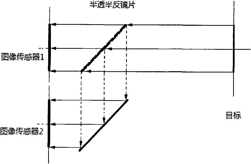
[0023] According to the existing conditions, in our final front-end optical system design, we adopted such as figure 2 The design of parallel optical axes shown, under the existing technical conditions, this design is guaranteed both in terms of process and imaging quality. The lens field of view of the...


PUM


Abstract

The invention relates to an infrared and glimmer multispectral fusion front end optical-mechanical structure, comprising a case, a wedge-shaped pedestal, a first light hole, a second light hole, a video wire, a glimmer image intensifier battery, a glimmer objective lens, a glimmer image intensifier, an infrared objective lens and an infrared detector; wherein the front end of the glimmer objective lens is provided with an optical wedge, the infrared objective lens and the infrared detector jointed behind the infrared objective lens form an infrared detection device, the glimmer objective lens and the glimmer image intensifier connected behind the glimmer objective lens form a glimmer detection device, the wedge-shaped pedestal is fixed in the interior of box body, the infrared detector and the glimmer image intensifier are fixed on the wedge-shaped pedestal, the infrared detection device and the glimmer detection device are placed downward in vertical direction, the optical axle of the infrared objective lens and the glimmer objective lens are in the same vertical plane and in parallel, the included angle of the optical axle is less than or equal to 0.1mRad; and the infrared objective lens and the glimmer objective lens have the same field of view. The structure is easy to process, registration accuracy is high, and imaging effect is good, thus having good market prospect.

Description

technical field [0001] The invention belongs to the field of front-end optical-mechanical structures of optoelectronic products, in particular to a front-end optical-mechanical structure for infrared and low-light multi-spectrum fusion with optical axis adjustment and parallel optical axes. Background technique [0002] The image matching fusion finally realized by the multi-spectral fusion image detection device, the realization of the image fusion technology must be based on the image registration. Image registration is to carry out spatial registration of each image participating in fusion. Image fusion has high requirements for registration accuracy. If the spatial error exceeds one pixel, ghosting will appear in the fusion result, which seriously affects the quality of the fusion image. The realization of image matching, on the one hand, lies in the realization of the registration algorithm in the later stage, and on the other hand, it depends on the optical design and...

Claims


Application Information

Patent Timeline
Patent Type & Authority Applications(China)
IPC IPC(8): G02B27/00G02B7/00
Inventor 常本康李力张俊举袁轶慧张绍禄钱芸生富荣国邱亚峰刘磊
Owner NANJING UNIV OF SCI & TECH
Why Eureka
Try Eureka