Overall self-detecting system and method

A self-inspection and complete machine technology, applied in the field of self-inspection, can solve problems such as low efficiency, low test efficiency, and insufficient test completeness

Inactive Publication Date: 2010-12-08
GLOBAL INNOVATION AGGREGATORS LLC
View PDF3 Cites 6 Cited by
  • Summary
  • Abstract
  • Description
  • Claims
  • Application Information

AI Technical Summary

Problems solved by technology

[0004] Obviously, using the existing test method, the control of the test is controlled manually, and the disadvantage is that: in order to complete the test of the SDH network element, more additional resources must be equipped, such as the network management console, SDH test instrument, etc.; Through different types of SDH test instruments, different types of SDH network elements are tested separately. Since SDH equipment is composed of different types of SDH network elements, it is impossible to test the overall status of SDH equipment, and the test is not complete enough. , it is difficult to achieve full-coverage testing; testing is time-consuming, manpower-intensive, and inefficient; for faults that occur during testing, the speed of positioning depends entirely on the professional quality of the testers who monitor the network management console, which is not conducive to operation
In the large-scale production and centralized delivery of SDH network elements, the above shortcomings are particularly obvious. It is the problem that the possible problems of each SDH network element cannot be quickly discovered, located, and repaired, and it is also the bottleneck of delivery guarantee.
To sum up, adopt existing technology, need to manually control the whole test process through the tester of monitoring gateway console; And also need the cooperative work of test instrument, to test each SDH network element in SDH equipment separately, cause Low reliability and accuracy of testing, low efficiency of testing, high cost of testing

Method used


Image

  • Overall self-detecting system and method
  • Overall self-detecting system and method
  • Overall self-detecting system and method

Examples


Embodiment Construction
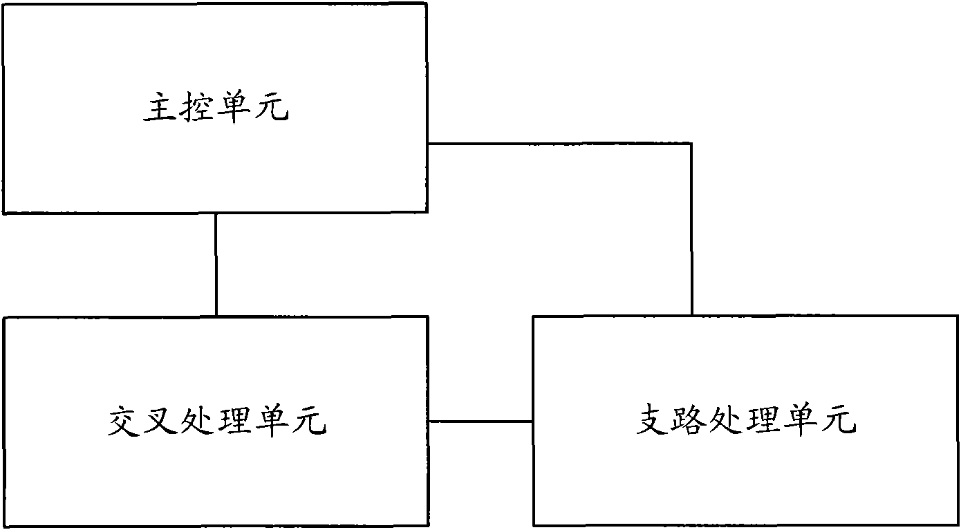
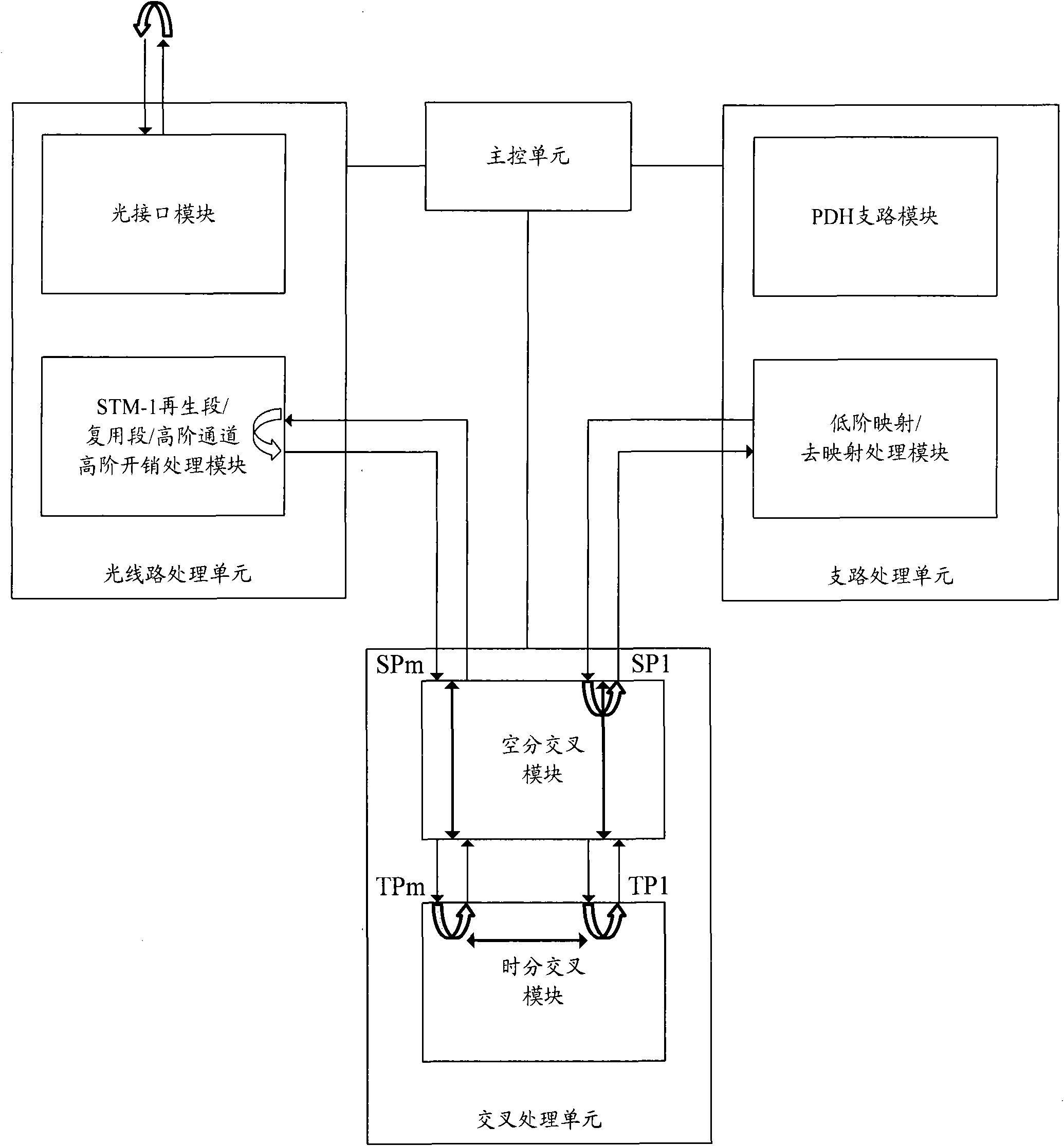
[0046] The basic idea of ​​the present invention is: under the control of the main control unit, the cross processing unit performs the cross loopback of the space division / time division mode in a traversal manner, and through the collaborative test of the cross processing unit and the branch processing unit, the branch processing unit The connectivity test is performed on the loopback link between the branch processing unit and the cross-connection processing unit, and the cross-loopback link inside the cross-connection processing unit to realize self-testing.

[0047] The implementation of the technical solution will be further described in detail below in conjunction with the accompanying drawings.

[0048] Such as figure 2 As shown, a whole machine self-inspection system includes: a main control unit, a cross processing unit, and a branch processing unit. Wherein, the main control unit is used to control the cooperative test of the cross processing unit and the branch pr...


PUM


Abstract

The invention discloses an overall self-detecting system. In the system, a cross processing unit is used for performing cross loop-back of a space division/time division mode in a traversal mode under the control of a main control unit; and a branch processing unit is used for performing connectivity test on a loop-back link between the branch processing unit and the cross processing unit and a cross loop-back link in the cross processing unit under the control of the main control unit. The invention also discloses an overall self-detecting method. The method comprises the following steps of:performing cross loop-back of the space division/time division mode in the traversal mode by the cross processing unit under the control of the main control unit, and performing connectivity test on the loop-back link between the branch processing unit and the cross processing unit and the cross loop-back link in the cross processing unit through cooperative test of the cross processing unit and the branch processing unit so as to realize self-detecting. The system and the method can improve the reliability, accuracy and efficiency of the test and reduce the cost of the test.

Description

technical field [0001] The invention relates to a self-testing technology, in particular to a system and method for self-checking the whole machine status of Synchronous Digital Transmission Hierarchy (SDH) equipment. Background technique [0002] SDH equipment is generally composed of a variety of line units that perform different functions, including power supply units, control units, service high- and low-level cross-connect units, overhead processing units, various types of outgoing line units, clock units, and so on. These components can be collectively referred to as SDH network elements. After the SDH network elements are processed in the production line, they must pass a series of functional and performance tests before they can be delivered to the factory. [0003] Existing methods for testing SDH network elements generally carry out networking tests according to actual applications, such as figure 1 As shown, the network management console and SDH test instrument ...

Claims


Application Information

Patent Timeline
Patent Type & Authority Applications(China)
IPC IPC(8): H04B10/08H04Q11/00H04L12/24H04L12/26
Inventor 任伟红
Owner GLOBAL INNOVATION AGGREGATORS LLC
Why Eureka
Try Eureka