
Method for cooling metal band and installation for implementing said method

A technology of metal strips and strips, which can be used in household refrigeration equipment, furnace cooling, lighting and heating equipment, etc., and can solve problems such as cost

Inactive Publication Date: 2010-12-15
COCKERILL MAINTENANCE & INGIE
View PDF14 Cites 6 Cited by
  • Summary
  • Abstract
  • Description
  • Claims
  • Application Information

AI Technical Summary

Problems solved by technology

The first disadvantage is that heat transfer is limited by the saturation temperature of noncondensable air or water in nitrogen, and the second is that when cooling with water and air or a mist of water and nitrogen, steel at high temperatures inevitably are subject to oxidation, which means that special treatments must then be implemented to remove the oxide film, such treatments can be expensive and sometimes impossible in some production lines such as electroplating lines

Method used


Image

  • Method for cooling metal band and installation for implementing said method
  • Method for cooling metal band and installation for implementing said method

Examples


Embodiment Construction

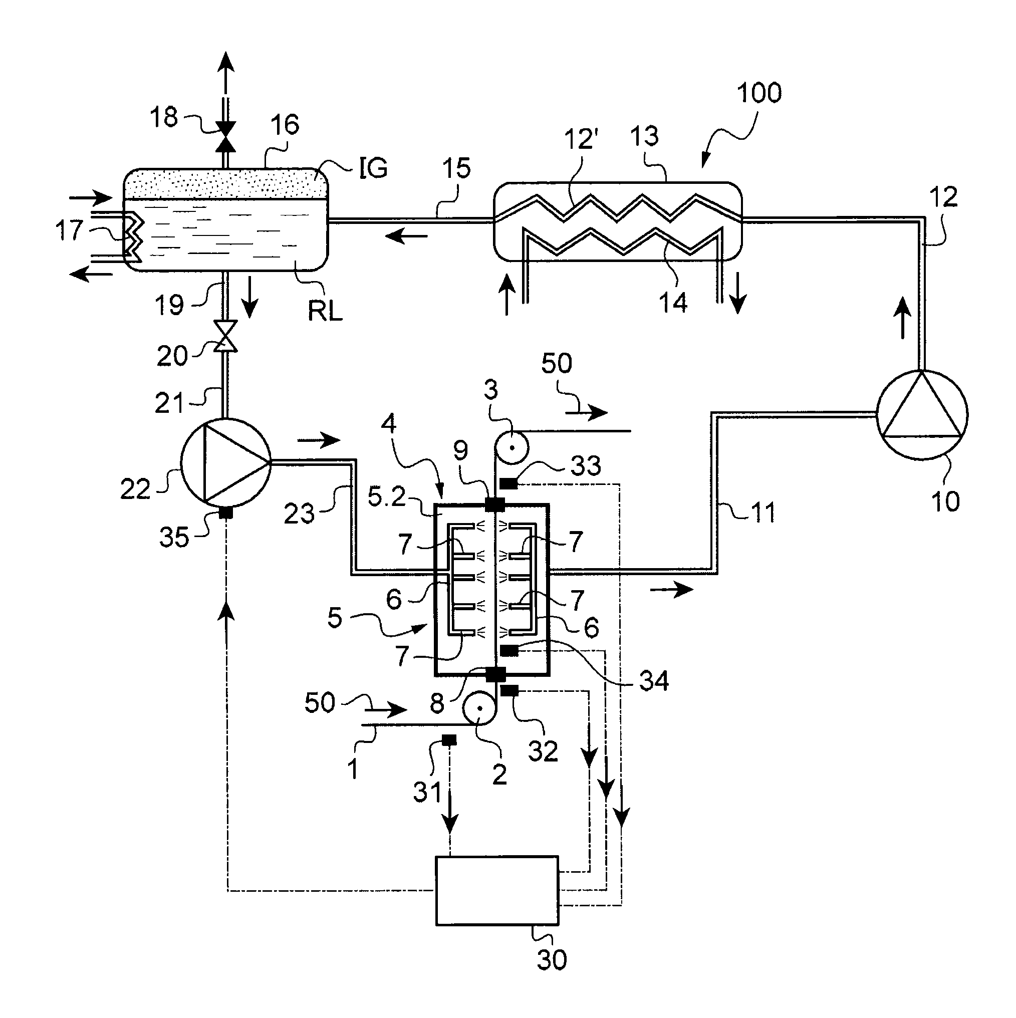
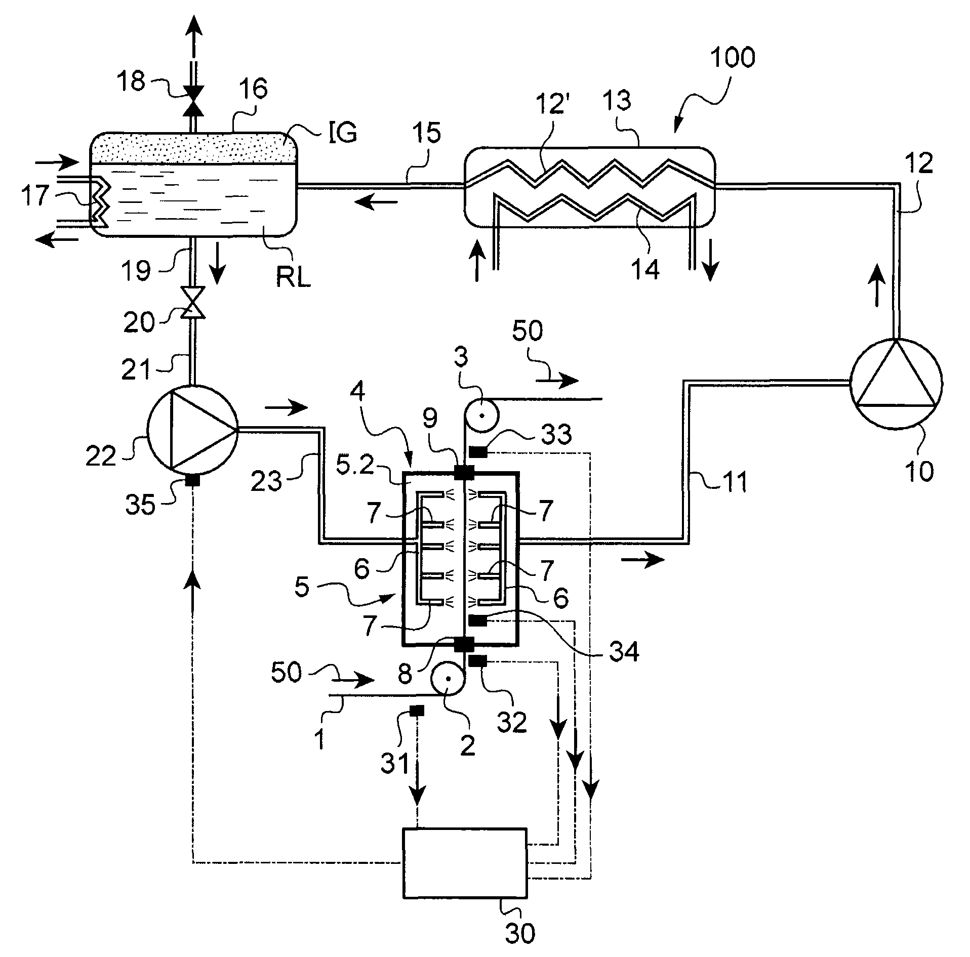
[0034] The only figure is a schematic diagram showing a device 100 for carrying out the cooling method according to the invention. The metal strip 1 moves through a cooling section 4 in a continuous heat treatment line, which may be an annealing line or a line for applying a metallic or organic coating.

[0035] According to the background art, the line along which the strip 1 passes is defined by bottom deflecting rollers 2 and top deflecting rollers 3 on each side of the cooling section 4 , the direction of movement of the metal strip 1 being indicated by arrow 50 .

[0036] The cooling section 4 comprises a cooling box 5 through which the metal strip 1 passes for cooling. The cooling box 5 is closed and the strip passes in a sealed manner through inlet and outlet airlocks 8 and 9, both shown schematically. They may consist of a flap system optionally cooperating with carrying rollers, which are well known in the field of continuous processing lines. By means of the inlet ...


PUM


Abstract

The invention relates to a method of cooling a metal strip traveling through a cooling section in a continuous heat treatment line. In accordance with the invention, the method consists in projecting a refrigerant medium into the cooling section (4) onto the surface of the strip (1) to be cooled, the medium being constituted for the most part by a phase-change substance that passes into the gaseous phase at a temperature that is lower than the temperature of the strip (1) and without oxidizing said strip so that energy is exchanged within an endothermic process by a change in the phase of said phase-change substance.

Description

technical field [0001] The invention relates to the cooling of a metal strip moving through the cooling section of a continuous heat treatment line, such as an annealing line or a line for applying a metallic or organic coating. Background technique [0002] In a continuous heat treatment line of the type described above, the metal strip is cooled in the cooling section by blasting air, usually a mixture of nitrogen and hydrogen, which passes through one or more cooling tubes equipped with associated holes or blast tubes. box. [0003] A constant consideration for cooling section designers is to cool the metal strip moving through the section as uniformly as possible while avoiding causing instability and / or vibrations to the moving metal strip. [0004] Document EP-A-1655383 discloses such a device in which the strip moves between two cooling boxes equipped with blowing ducts inclined at an angle directed upstream and / or or downstream, and also towards the edge of the str...

Claims


Application Information

Patent Timeline
Patent Type & Authority Applications(China)
IPC IPC(8): C21D9/573
CPCF25D3/12C21D9/573F27B9/12F27D9/00
Inventor M·钮默M·佐格哈博D·克隆迪克D·阿布多S·兰格威P·杜波依斯
Owner COCKERILL MAINTENANCE & INGIE
Learn More