
Method for determining current rigidity and displacement rigidity of permanent magnet biased hybrid magnetic bearing

A hybrid magnetic bearing and permanent magnet bias technology, applied in the direction of bearings, shafts and bearings, mechanical equipment, etc., can solve the problems of not reflecting the system characteristics of the magnetic bearing control system, unable to install the magnetic bearing, ignoring the magnetic circuit coupling of the magnetic bearing, etc.

Inactive Publication Date: 2010-12-15
BEIHANG UNIV
View PDF4 Cites 24 Cited by
  • Summary
  • Abstract
  • Description
  • Claims
  • Application Information

AI Technical Summary

Problems solved by technology

[0005] At present, there are mainly two types of determination methods for current stiffness and displacement stiffness. One is theoretical calculation methods, such as "a method for determining dynamic current stiffness of magnetic bearings based on eddy current effect" disclosed in Chinese patent "ZL200710120705.7". The method uses the magnetic bearing design parameters to calculate the current stiffness and displacement stiffness, and considers the influence of the eddy current effect, but ignores the influence of magnetic circuit coupling and magnetic flux leakage between the magnetic bearings, which cannot reflect the normal operation of the magnetic bearing control system. System characteristics; the second is the test method, by installing a load cell in the magnetic bearing, changing the current size and the position of the rotor in the gap, measuring the size of the electromagnetic force, and obtaining the current stiffness and displacement stiffness parameter values, although this method has It has the advantages of simple and clear physical meaning and high precision, but it cannot be installed in the existing magnetic bearing due to the influence of factors such as mechanical size and installation difficulty

Method used


Image

  • Method for determining current rigidity and displacement rigidity of permanent magnet biased hybrid magnetic bearing
  • Method for determining current rigidity and displacement rigidity of permanent magnet biased hybrid magnetic bearing
  • Method for determining current rigidity and displacement rigidity of permanent magnet biased hybrid magnetic bearing

Examples


Embodiment Construction

[0039] specific implementation plan

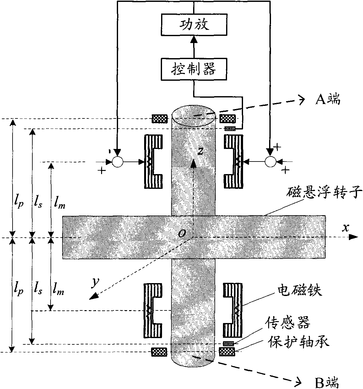
[0040] Such as figure 1 As shown, the permanent magnet bias hybrid magnetic bearing control system consists of a permanent magnet bias hybrid magnetic bearing, a power amplifier, a magnetic levitation rotor, a displacement sensor and a controller. The displacement sensor detects the displacement of the electromagnet rotor from the reference point. The controller calculates the control signal according to the displacement deviation. position. Since the protective bearing is closer to the magnetic levitation rotor than the permanent magnetic bias hybrid magnetic bearing, the magnetic levitation rotor is supported on the protective bearing when it is not levitating, preventing the permanent magnetic bias hybrid magnetic bearing from being damaged due to contact with the magnetic levitation rotor .

[0041] In this example, the parameters of the permanent magnetic bias hybrid magnetic bearing and the magnetic levitation rotor are as follows...


PUM


Abstract

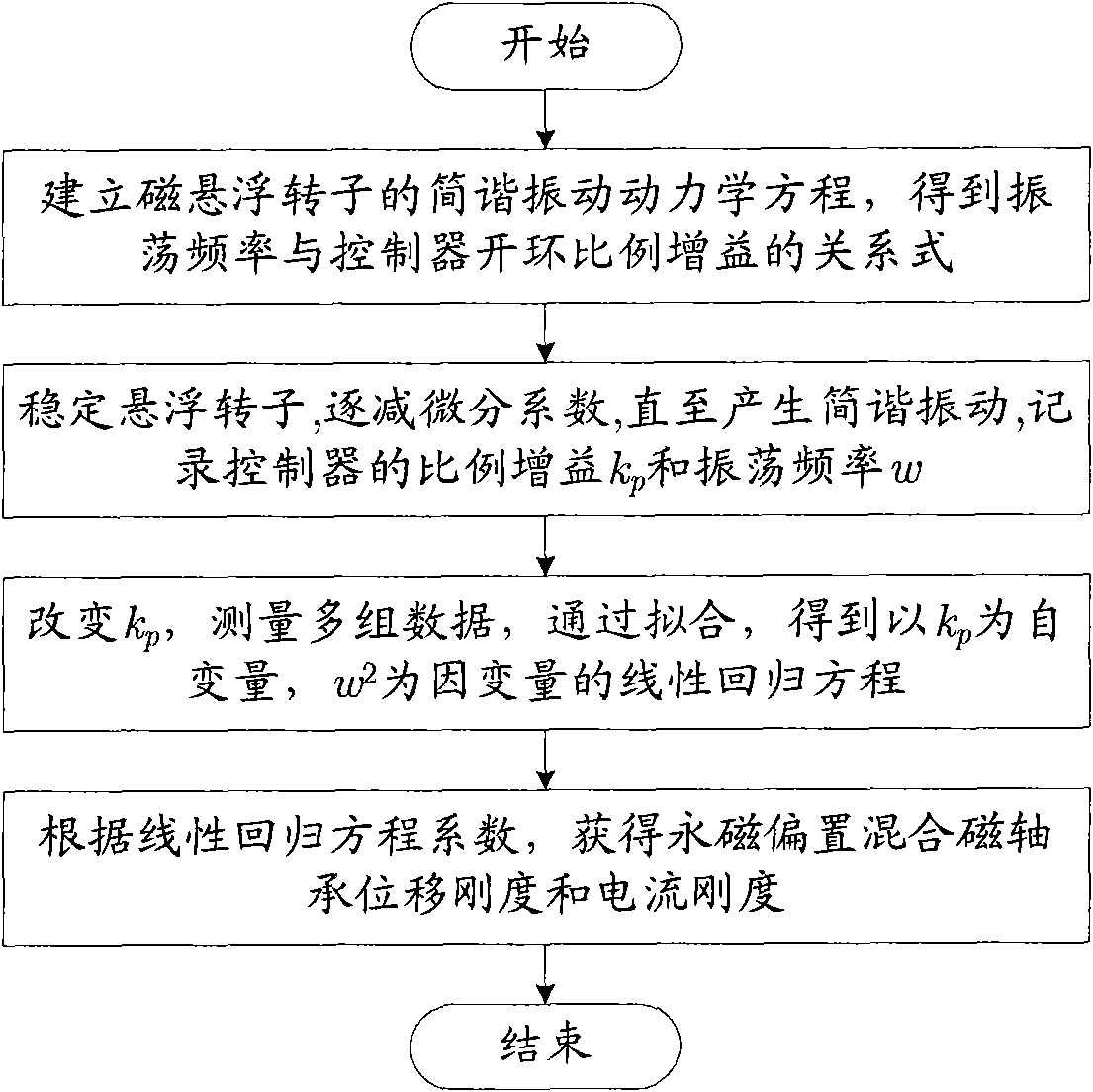
The invention discloses a method for determining current rigidity and displacement rigidity of a permanent magnet biased hybrid magnetic bearing. The method comprises the following steps of: establishing relation among the current rigidity, the displacement rigidity, controller proportional gain and oscillation frequency of simple harmonic motion of a magnetic suspension rotor according to a kinetic equation of the simple harmonic motion of the magnetic suspension rotor; obtaining related data about the controller gain and the oscillation frequency of the simple harmonic motion of the magnetic suspension rotor by adjusting the controller proportional gain; and determining the current rigidity and the displacement rigidity of the magnetic suspension rotor by fitting the coefficient of a unitary linear regression equation. The method has the advantages of simplicity and practicability and can be applied to the analysis and design of a magnetic suspension rotor control system.

Description

technical field [0001] The invention relates to a method for determining current stiffness and displacement stiffness of a permanent magnet bias hybrid magnetic bearing, which can be used for analysis and design of a magnetic levitation rotor control system. Background technique [0002] Magnetic bearings are an ideal new bearing developed after sliding bearings, rolling bearings and hydrostatic bearings. They have the advantages of no contact, no wear, and high speed. Magnetic bearings can be divided into permanent magnetic bearings, active magnetic bearings and permanent magnetic bias hybrid magnetic bearings according to the way the magnetic force is provided. The main disadvantages of permanent magnetic bearings are low stiffness and uncontrollability. The main disadvantages of active magnetic bearings are large volume and power consumption, while permanent magnet bias hybrid magnetic bearings use permanent magnets to replace the static bias generated by excitation curre...

Claims


Application Information

Patent Timeline
IPC IPC(8): F16C32/04
Inventor 房建成郑世强李海涛谢进进李文琢马纪军
Owner BEIHANG UNIV
Learn More