

Mixing adjustable excited non salient pole rotor for large air-cooled turbine generator
A technology of turbogenerator and hidden pole rotor, which is applied in the direction of magnetic circuit rotating parts, magnetic circuit shape/style/structure, etc., which can solve the problem of high rotor temperature and achieve the effect of reducing temperature
- Summary
- Abstract
- Description
- Claims
- Application Information
AI Technical Summary
Problems solved by technology
Method used
Image

Examples
specific Embodiment approach 1
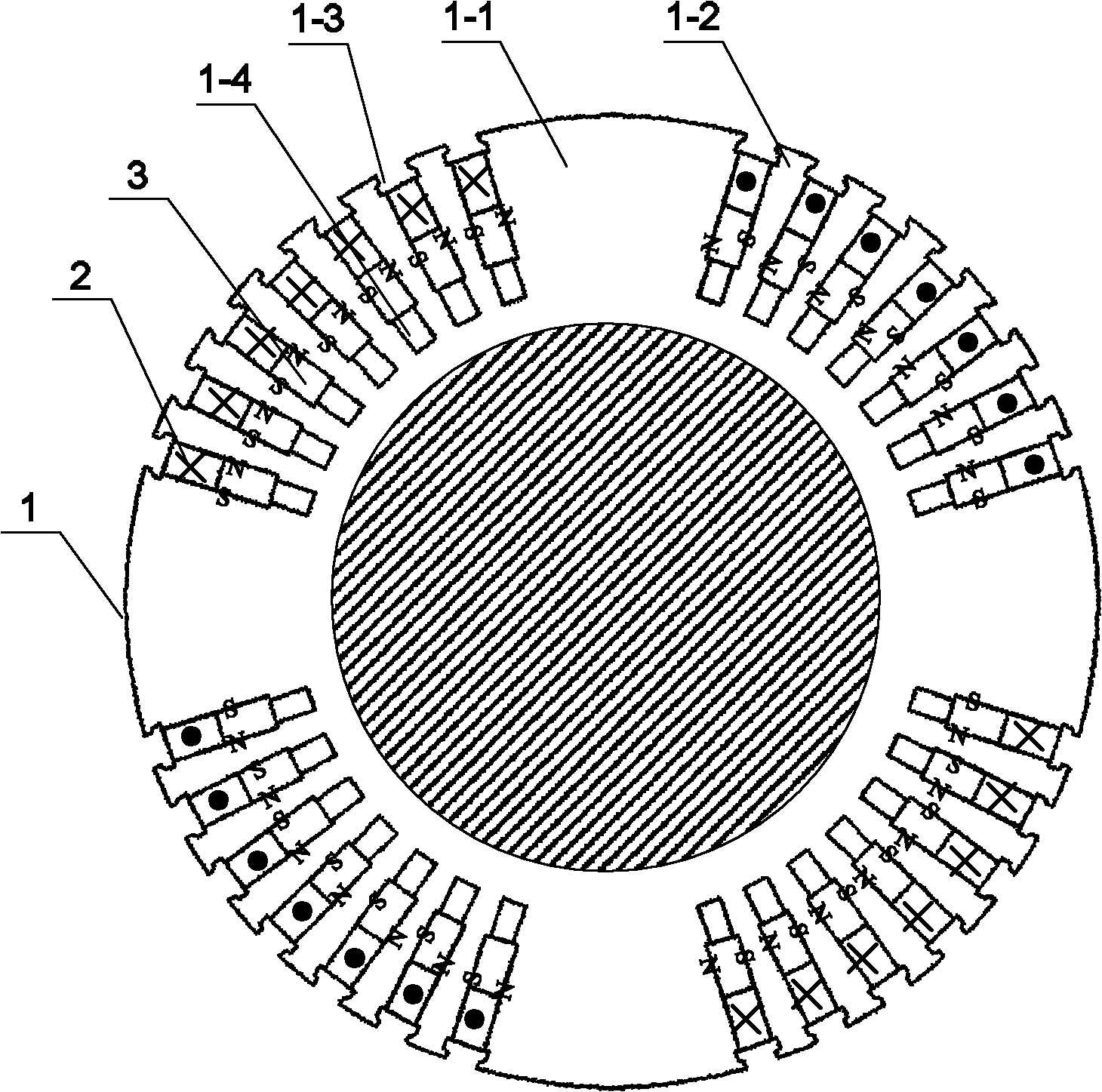
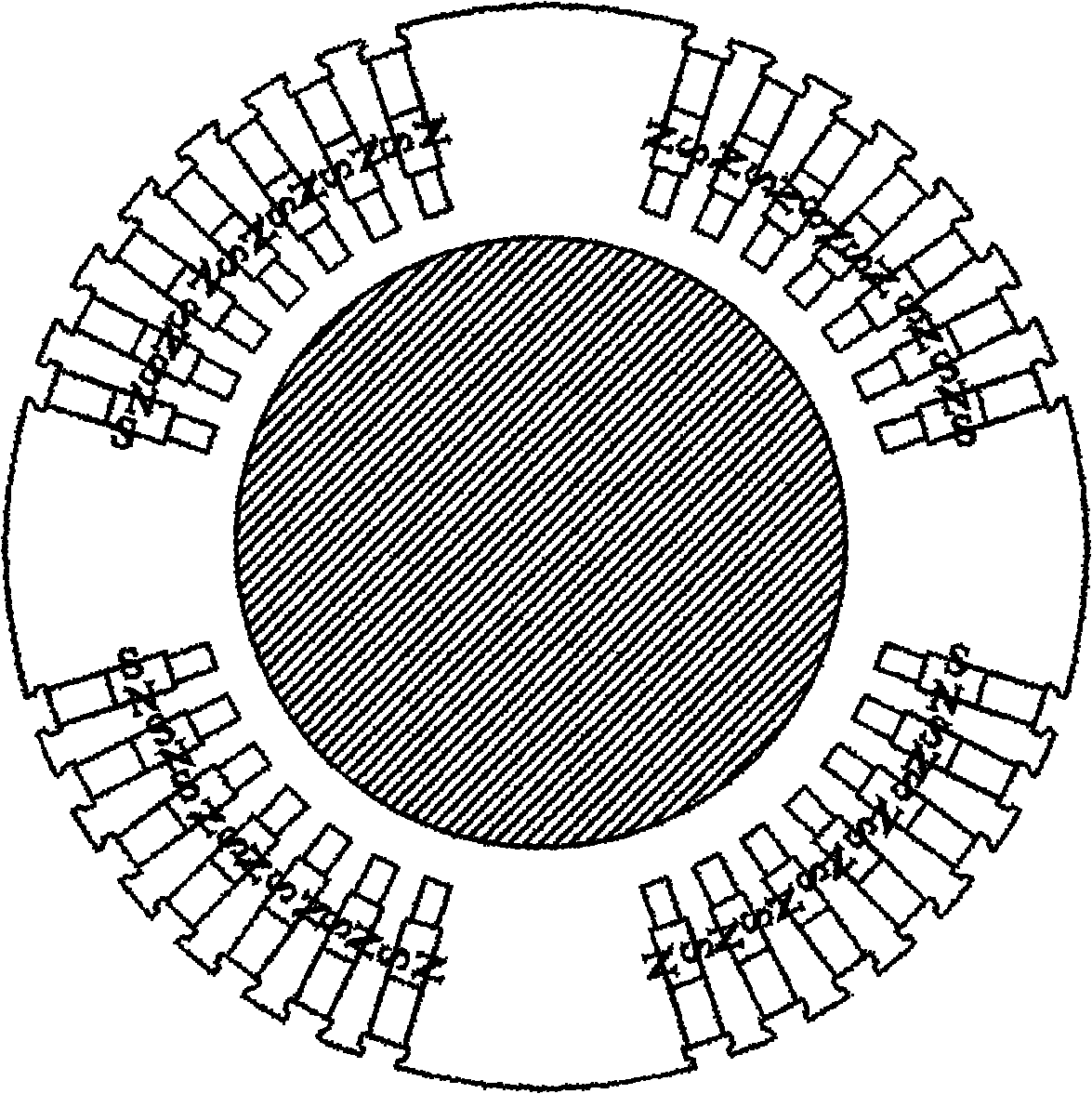
[0015] Specific implementation mode one: the following combination Figure 1 to Figure 6 Describe this embodiment. This embodiment includes a quadrupole rotor core 1 and two sets of rotor windings 2. Four large teeth 1-1 and four groups of small teeth 1-2 of the quadrupole rotor core 1 are arranged at intervals. Adjacent teeth There are tooth slots 1-3 between the tooth slots, and the bottom center of each tooth slot 1-3 has a rotor auxiliary slot 1-4, and the slot width of the rotor auxiliary slot 1-4 is smaller than the slot width of the tooth slot 1-3.
[0016] It also includes a plurality of permanent magnets 3, a permanent magnet 3 is embedded in the bottom of each slot 1-3, and a set of rotor windings 2 is wound on every two groups of small teeth 1-2, and the rotor winding 2 is located above the permanent magnets 3.
[0017] In this embodiment, a shoulder structure is formed at the junction of the tooth slots 1-3 and the rotor auxiliary slots 1-4, and this shoulder struc...
specific Embodiment approach 2
[0019] Specific implementation mode two: the following combination Figure 1 to Figure 6 This embodiment will be described. This embodiment is a further description of the first embodiment. The magnetic field generated by the rotor winding 2 is in the same direction as the magnetic field formed by the permanent magnet 3 . Other components and connections are the same as those in Embodiment 1.
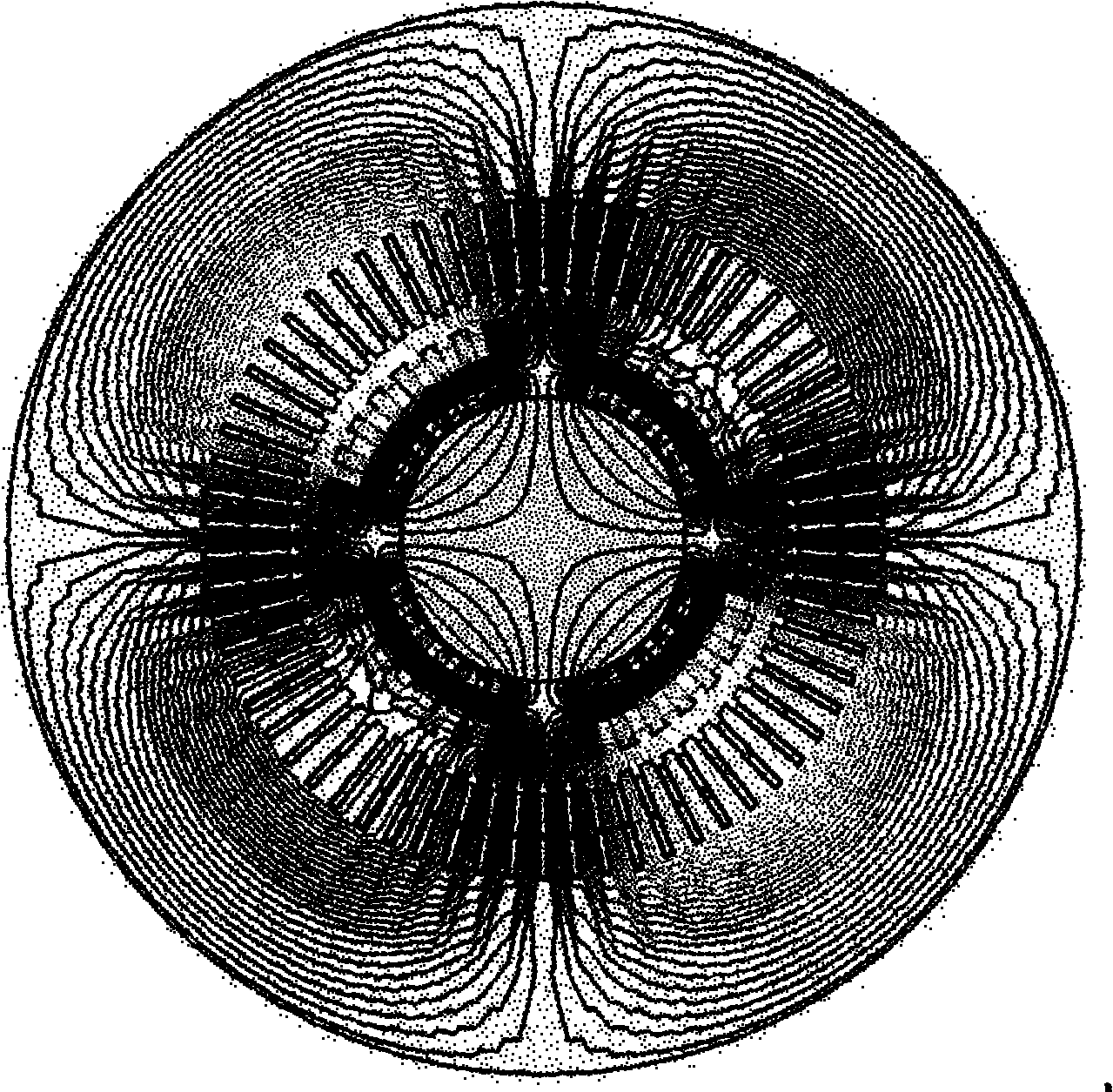
[0020] image 3 Shown in this embodiment, when the current of the rotor winding 2 is zero, the distribution diagram of the magnetic force lines generated by the permanent magnet 3; Figure 5 Shown is a distribution diagram of the flux lines of the magnetic field formed by the rotor winding 2 . Depend on image 3 and Figure 5 It can be seen that the magnetic field generated by the electric excitation of the rotor winding 2 and the individual excitation of the permanent magnet 3 is a quadrupole distribution, and the magnetic pole distribution is the same. When the rotor winding 2 on...
PUM
 Abstract
Description
Claims
Application Information