Tilt device

A technology of tilting device and workbench, which is applied in the direction of positioning device, tool changing device, manufacturing tools, etc., can solve the problems of coolant dispersion and reduction of machining accuracy, so as to improve machining accuracy, reduce time and labor, and improve rotation positioning accuracy Effect

Active Publication Date: 2012-06-20
三惠C&C株式会社 +3
View PDF1 Cites 0 Cited by
  • Summary
  • Abstract
  • Description
  • Claims
  • Application Information

AI Technical Summary

Problems solved by technology

In addition, the following problems are caused: the processing accuracy is lowered because the chips generated by machining the workpiece with the tool are accumulated on the workpiece and the tilting table; More time and labor to remove chips and coolant spreads everywhere

Method used


Image

  • Tilt device
  • Tilt device
  • Tilt device

Examples


Embodiment Construction

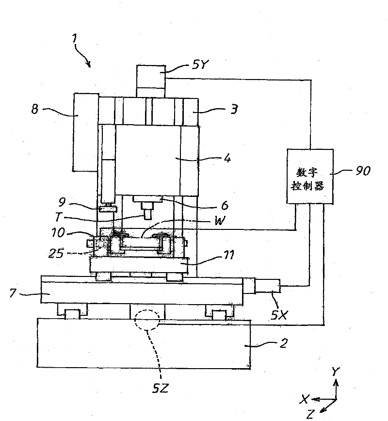
[0030] A tilting device in an embodiment of the present invention will be described below with reference to the accompanying drawings. Such as figure 1 As shown, the tilting device 10 is fixed on a table 11 of a machine tool such as a vertical machining center 1 . In the machining center 1, a column 3 is vertically provided on a bed 2, and a spindle head 4 is mounted on the column 3 so as to be movable in the vertical direction, and is moved by a ball screw rotationally driven by a servo motor 5Y. A tool spindle 6 is supported in the spindle head 4 so as to be rotatable about a vertical axis, and is rotationally driven by a built-in motor (not shown). The tool spindle 6 is provided with a tool attachment device that detachably holds a tool T inserted into a tool attachment hole formed at the lower end of the tool spindle 6 . On the bed 2, a slide plate 7 is mounted movable in the horizontal front-rear direction, and moved in the Z-axis direction by a ball screw rotationally...


PUM


Abstract

In the course of a machining of a workpiece with a tool, a drive spindle with a tilt table secured thereto of a tilt device provided on a work table of a machining center is rotated by a direct drive motor to control the relative angular position between the tool and the workpiece, and within a predetermined period of time in the course of a machining, the direct drive motor is rotated at a high speed with a spindle head and the work table of the machining center kept away to rotate the drive spindle and hence, the tilt table at a high speed, so that chips and cutting lubricant can be shaken from the workpiece and the tilt table.

Description

technical field [0001] The invention relates to a tilting device equipped on a machine tool for rotating an attached workpiece to a desired angular position. Background technique [0002] As such a reclining device in the prior art, such a reclining device as disclosed in Patent Document 1 is known, for example. In the tilting device described in Patent Document 1, a pair of pivot shafts 21A, 21B having a common pivot axis O are supported outwardly in U-shaped projections on opposite sides of the tilt table 20 , and the pivot shafts 21A, 21B are supported by a pair of support portions 11a, 11b erected on the support table via bearings 14A, 14B. The tilt table 20 is provided with a turn table 25 which detachably supports a pallet 26 for attaching a workpiece W thereon, and which rotates about an axis perpendicular to the pivot axis O. As shown in FIG. The servo motors 33A, 33B rotate the pivot shafts 21A, 21B through the worm 32 and the worm gear 31, and the encoder 27 atta...

Claims


Application Information

Patent Timeline
Patent Type & Authority Patents(China)
IPC IPC(8): B23Q1/64B23Q1/52B23Q3/155B23Q11/00
CPCB23Q1/52B23Q11/0042B23Q1/64Y10T409/304088Y10T409/305768Y10T409/305824Y10T409/308792Y10T409/30896Y10T483/10Y10T483/1733Y10T483/1736
Inventor 坂根一广镰田祐子
Owner 三惠C&C株式会社
Why Eureka
Try Eureka