
Solar frying device

A technology of solar energy and heat collectors, applied in the field of food heating equipment, can solve problems such as not easy to carry, inconvenient to use, and paraboloids are easily affected by dust and wind

Inactive Publication Date: 2015-05-27
江苏晟风新能源发展有限公司
View PDF7 Cites 0 Cited by
  • Summary
  • Abstract
  • Description
  • Claims
  • Application Information

AI Technical Summary

Problems solved by technology

[0002] At present, the solar cooking pots on the market are mainly concentrating solar cooking pots. Most of the concentrating solar cooking pots are bulky and heavy, and are not easy to carry. The more typical one is the parabolic concentrating cooking pot, and the concentrating focus is located outside the pot. The bottom is unsafe to operate and inconvenient to use. The parabolic surface is easily affected by dust and wind. More importantly, the parabolic concentrating cooking pan has a greater impact on the angle of the sun's rays, and there is a slight deviation. The position of the concentrating focus Deviated from the pot body, it needs to be used with an expensive solar tracking system, so the concentrating solar cooking pot is not practical, so it has not been popularized until now

Method used


Image

  • Solar frying device
  • Solar frying device
  • Solar frying device

Examples


Embodiment 1

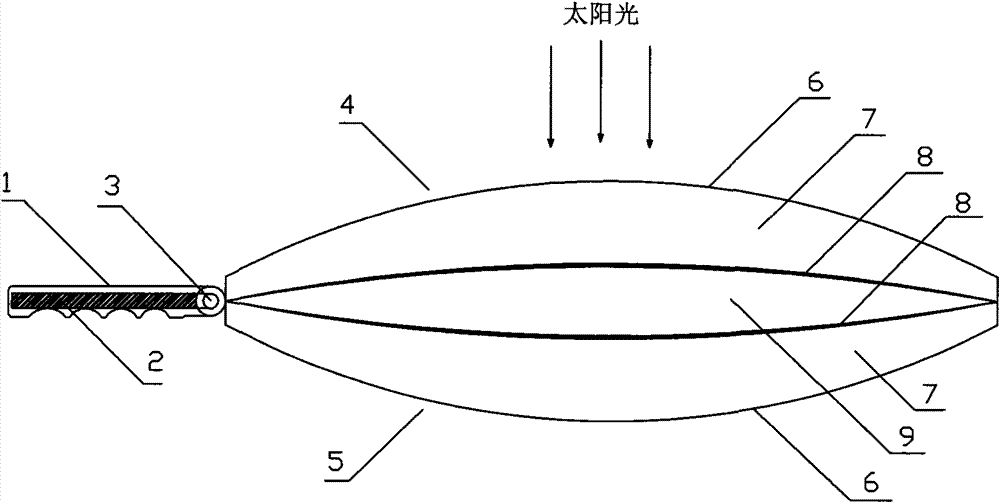
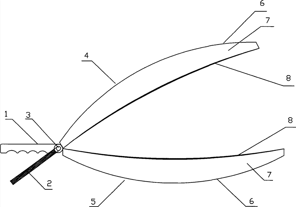
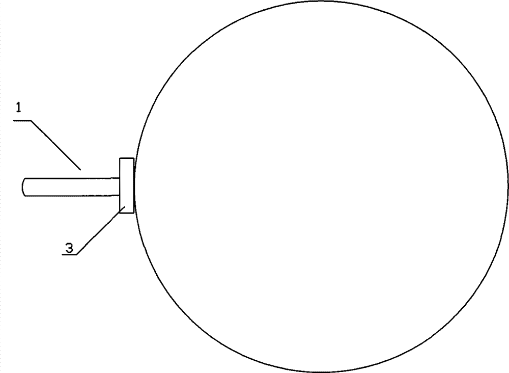
[0011] Such as figure 1 , figure 2 , The upper cover 4 and the lower cover 5 are both composed of solar vacuum glass heat collectors, and the upper cover 4 and the lower cover 5 are back-buckled together in a symmetrical dish shape, and the edges of the upper cover 4 and the lower cover 5 are tightly combined with high temperature silicone rubber pads , The high-temperature silicone rubber at the edge only plays a role of sealing and buffering. The upper cover 4 and the lower cover 5 are both thick in the middle and thin in the edge. The space formed by the two inner concave surfaces 8 is used to hold food, that is, food Space 9, the outer convex surface 6 of the upper cover 4 and the lower cover 5 are made of transparent glass, the inner concave surface 8 is made of stainless steel, the middle interlayer formed by the outer convex surface 6 and the inner concave surface 8 is a vacuum 7, the upper cover 4 and The vacuum surface of the inner concave surface 8 of the lower cover ...

Embodiment 2

[0013] Based on the first embodiment, after the upper cover 4 and the lower cover 5 are back-buckled into one body, the handle end is replaced with a belt pulley 15. There are bearings 14 at both ends of the rotation center line AA1 of the handle, and both ends are embedded in the bracket 10. , Under the action of the motor 12, the upper cover 4 and the lower cover 5 are continuously exchanged up and down through the belt 13, that is, rotate around AA1, and play the role of "bumping the spoon" during the cooking process. The energy of the motor 12 comes from the solar panel 11. The main shaft of the motor 12 can also be directly connected to the handle to directly drive the upper and lower covers to flip, or the motor 12 can be replaced with an eccentric motor to directly drive the upper and lower covers to vibrate left and right or up and down, which can also play a role of "flipping the spoon".


PUM


Abstract

The invention aims to provide a solar frying device with portability, easy and safe operation and little solar ray angle influence without being influenced by dust and wind. The solar frying device can generate high temperature by utilizing sunlight to collect heat in a short time to fry foods and is characterized in that an upper cover and a lower cover are made of solar vacuum glass heat collectors and reversely buckled together to form a symmetrical disc shape, the frying device is arranged under sunlight, and the positions of the upper cover and the lower cover are repeatedly turned over so that two internally concave surfaces are uniformly heated. Because the upper cover and the lower cover are made of the solar vacuum glass heat collectors, and black body heat-absorbing layers are heated to continuously accumulate heat and continuously increase the temperatures under the thermal insulation action of a vacuum interlayer so that heat is continuously transferred to the internally concave surfaces made of stainless steel, and the internally concave surfaces continuously transfers the heat to the foods in a food space to fry the foods until cooked.

Description

Technical field: [0001] The invention relates to the field of food heating equipment, in particular to a solar heating type cooking pan. technical background: [0002] At present, the main method of solar cooking wok on the market is concentrating solar cooking wok. Most concentrating solar cooking woks are bulky and difficult to carry. The parabolic concentrating cooking wok is more typical, and the focal point is outside the pot. The bottom is not safe to operate and inconvenient to use. The parabolic surface is easily affected by dust and wind. More importantly, the parabolic concentrating cooking pan has a greater impact on the angle of the sun’s rays, with a slight deviation, and the focus position Deviating from the pot body, it needs to be used with an expensive solar tracking system, so the concentrated solar cooking wok is not practical, and it has not been popularized until now. Summary of the invention: [0003] In order to solve the above drawbacks, the purpose of the...

Claims


Application Information

Patent Timeline
Patent Type & Authority Patents(China)
IPC IPC(8): A47J27/00F24J2/00F24J2/48F24J2/46H02K7/10H02S40/44
CPCY02E10/40Y02E10/50Y02E10/60
Inventor 时扬
Owner 江苏晟风新能源发展有限公司
Learn More