Horizontal dense-phase circulating fluidizing dry-tower desulfurization device

A circulating fluidization and desulfurization device technology, applied in the field of environmental engineering, can solve the problems of increasing the chance of collision between desulfurizing agent and flue gas, increasing the chance of collision between desulfurizing agent and flue gas, and occupying a large area, so as to save power consumption , easy maintenance and low operating costs

Active Publication Date: 2010-12-22
BEIJING BEIKE ENVIRONMENTAL ENG CO LTD
View PDF6 Cites 2 Cited by
  • Summary
  • Abstract
  • Description
  • Claims
  • Application Information

AI Technical Summary

Problems solved by technology

[0004] The purpose of the present invention is to solve the problems existing in the existing dense-phase circulating fluidized dry tower desulfurization device, such as high energy consumption, easy stepping bed blockage, large floor area, etc. , under the condition that the reaction time remains unchanged, the route of the flue gas is extended, thereby increasing the chance of collision between the desulfurizer and the flue gas, and improving the desulfurization rate; the dense phase chamber is horizontal, the circulating fluidized chamber is vertical, and A stirring shaft is added to the phase chamber to increase the chance of collision between the desulfurization agent and the flue gas, resulting in an increase in desulfurization efficiency

Method used


Image

  • Horizontal dense-phase circulating fluidizing dry-tower desulfurization device
  • Horizontal dense-phase circulating fluidizing dry-tower desulfurization device
  • Horizontal dense-phase circulating fluidizing dry-tower desulfurization device

Examples


Embodiment Construction

[0028] Embodiments of the present invention will be described in detail below in conjunction with the accompanying drawings.

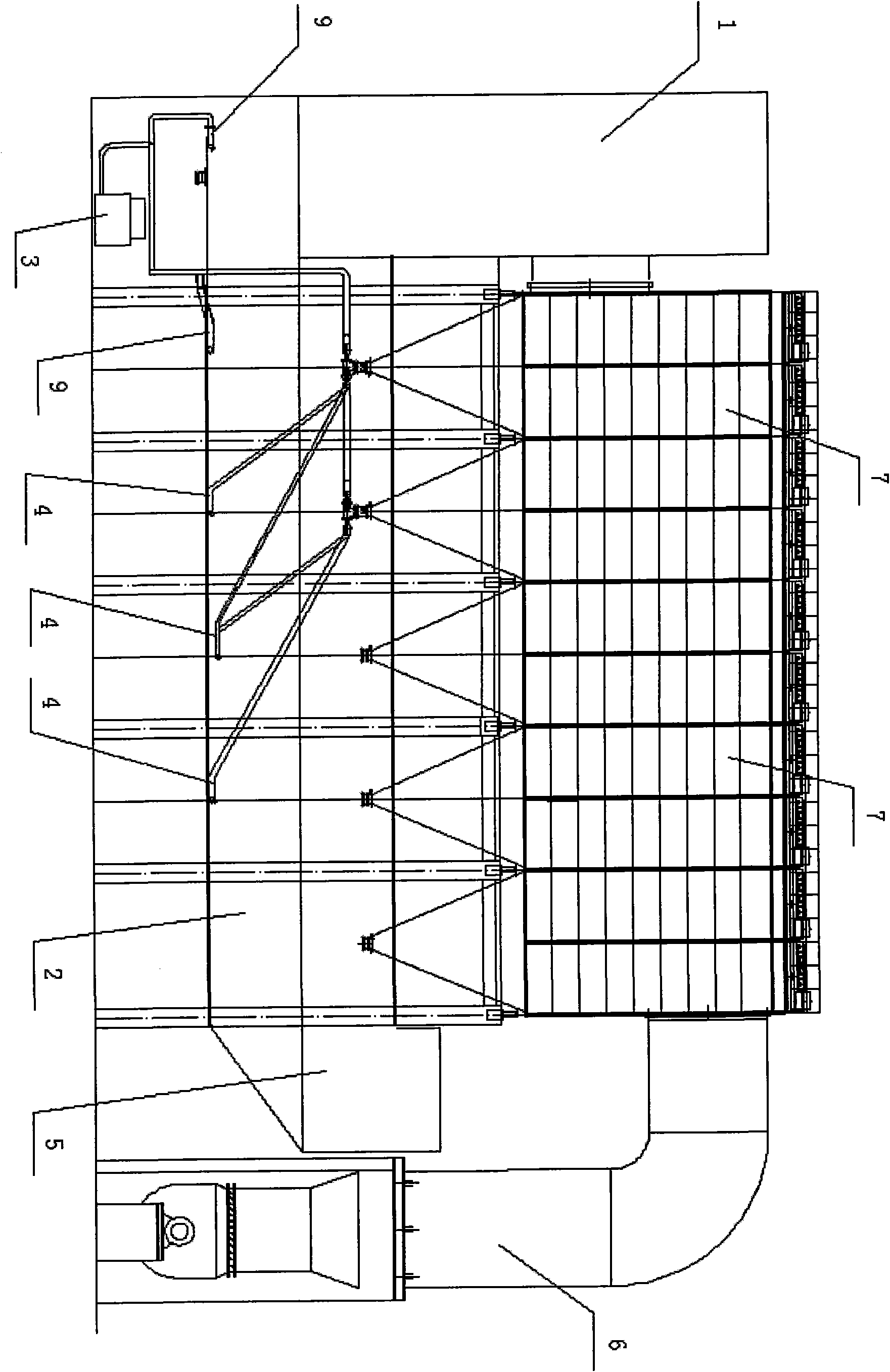
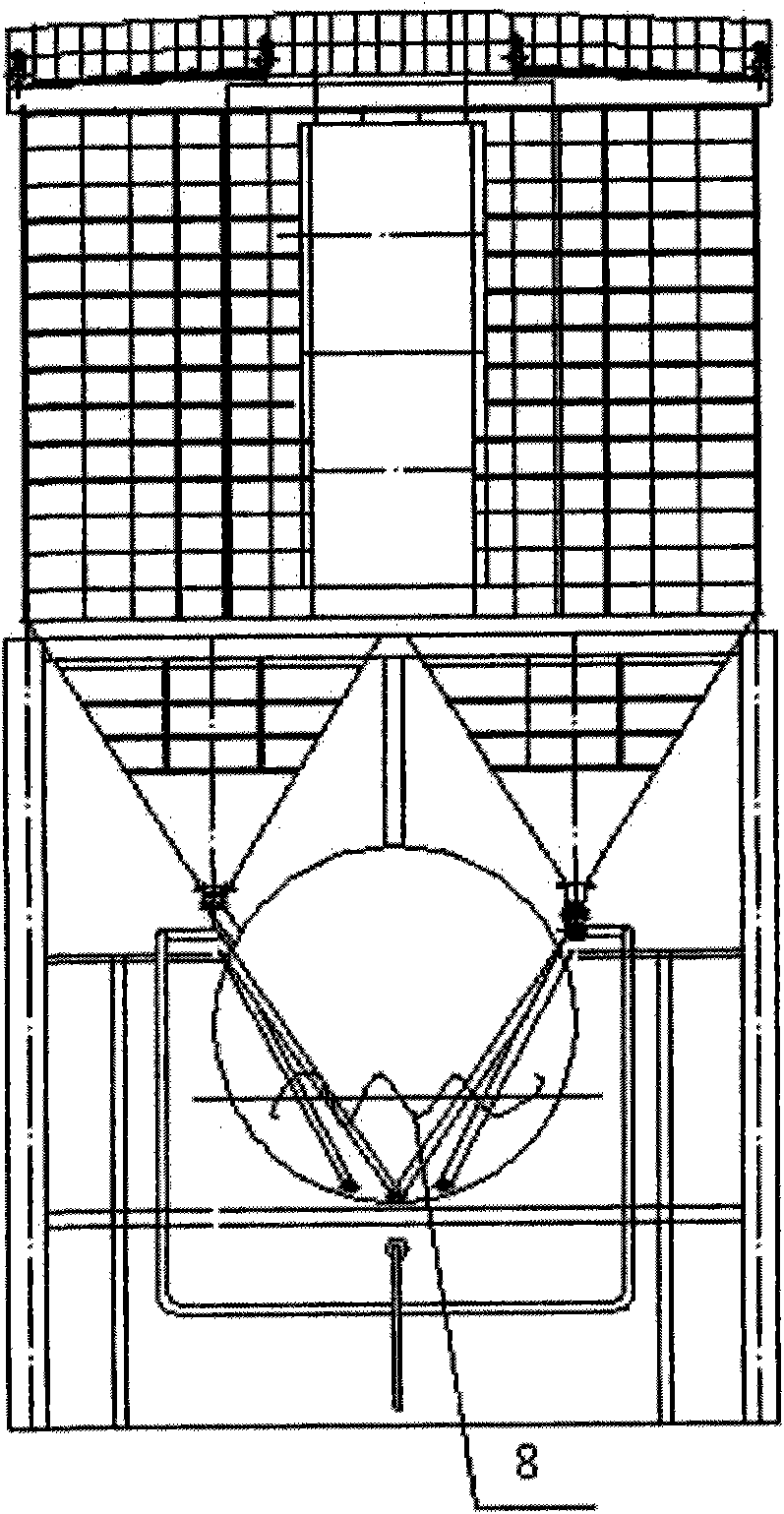
[0029] like figure 1 As shown, the present invention is a horizontal dense-phase circulating fluidized dry tower desulfurization device. Compressor 6, bag filter 7; the circulating fluidized chamber 1 of the present invention is vertical, and is arranged at the leftmost end of the device, and the flue gas and desulfurizing agent fully contact and react in the circulating fluidized chamber 1 to realize desulfurization. The dense-phase chamber 2 is horizontal, set on the right side of the circulating fluidized chamber 1, and communicated with the circulating fluidized chamber 1; and because the horizontal part is arranged under the bag filter, it saves space for the detachment device area. The bag filter 7 is above the dense phase chamber 2 . The desulfurizing agent separated from the bag filter 7 can enter the dense phase chamber 2 again to realize r...


PUM


Abstract

The invention relates to a horizontal dense-phase circulating fluidizing dry-tower flue-gas desulfurization device belonging to the field of environmental engineering. The horizontal dense-phase circulating fluidizing dry-tower flue-gas desulfurization device comprises a circulating fluidizing chamber (1), a dense-phase chamber (2), a Roots blower (3), a feeding pipe (4), a flue gas inlet (5), a booster fan (6) and a bag-type dust collector (7) and is characterized in that a stirring shaft (8), a gas pipe (9) and a gas distribution pipe (10) are arranged, wherein the stirring shaft (8) is mounted in the dense-phase chamber and provides more collision chances for a desulfurizer and the flue gas in the dense-phase chamber so as to improve the desulfurization efficiency; the gas pipe (9) is connected with the Roots blower for providing the circulating fluidizing chamber and the dense-phase chamber with fluidized wind power; and the gas distribution pipe (10) is mounted at the tail ends of the gas pipe (9) and the feeding pipe (4), and the wind power of the Roots blower is blown to all directions through the gas distribution pipe (10). The invention solves the problems of higher energy consumption, easy foot pedal blockage, great occupied area, and the like existing in the traditional dense-phase circulating fluidizing dry-tower desulfurization device and improves the desulfurization efficiency.

Description

technical field [0001] The invention relates to a horizontal dense-phase circulating fluidized dry tower flue gas desulfurization device, which belongs to the field of environmental engineering. Background technique [0002] Reducing sulfur dioxide emissions is the focus of environmental protection during the country's "Eleventh Five-Year Plan" period, and it is one of the key links for the iron and steel industry to reduce environmental pollution. The main source of sulfur dioxide pollution in the iron and steel industry is the sintering process, and its emissions account for more than 50% of the total emissions in the iron and steel industry. [0003] The dense coherent tower processing technology developed in recent years has obvious advantages. However, in the existing dense-phase circulating fluidized desulfurization equipment, there is only one chamber in the dense-phase circulating fluidized desulfurization equipment, such as Chinese patent: ZL200720103180.1 "a dense...

Claims


Application Information

Patent Timeline
Patent Type & Authority Applications(China)
IPC IPC(8): B01D53/83B01D53/48B01J8/24
Inventor 宋存义汪莉邢奕钱大益常冠钦
Owner BEIJING BEIKE ENVIRONMENTAL ENG CO LTD
Why Eureka
Try Eureka