Microwave continuous freeze-drying system

A technology of freeze-drying and microwave, which is applied in the direction of drying, drying machine, progressive drying machine, etc., can solve the problems of high utilization rate, high cost and long freeze-drying cycle of vacuum water catcher, and achieve the elimination of microwave vacuum electric field Breakdown phenomenon, efficiency improvement, high utilization effect

Inactive Publication Date: 2010-12-22
周川
View PDF1 Cites 21 Cited by
  • Summary
  • Abstract
  • Description
  • Claims
  • Application Information

AI Technical Summary

Problems solved by technology

This system is aimed at the defects of 15-30 hours for traditional freeze-drying (15-30 hours for materials to be freeze-dried to qualified moisture), long freeze-drying cycle, huge equipment, expensive cost, and low efficiency. The freeze-drying time is shortened, and the problem of microwave breakdown discharge under the vacuum pressure range required for freeze-drying is solved. The sealing performance is good, and the generated microwave cannot break down the electric field. The feeding, freeze-drying, and discharging of the freeze-drying device of the present invention are simultaneously high utilization rate; due to the use of a composite freeze-drying warehouse and continuous feeding and discharging methods, the freeze-drying process of materials in the vacuum microwave cavity is continuous, and the utilization rate of the vacuum water catcher is high; the freeze-drying rate is fast and can effectively Realize automatic industrial application

Method used


Image

  • Microwave continuous freeze-drying system
  • Microwave continuous freeze-drying system
  • Microwave continuous freeze-drying system

Examples


Embodiment 1

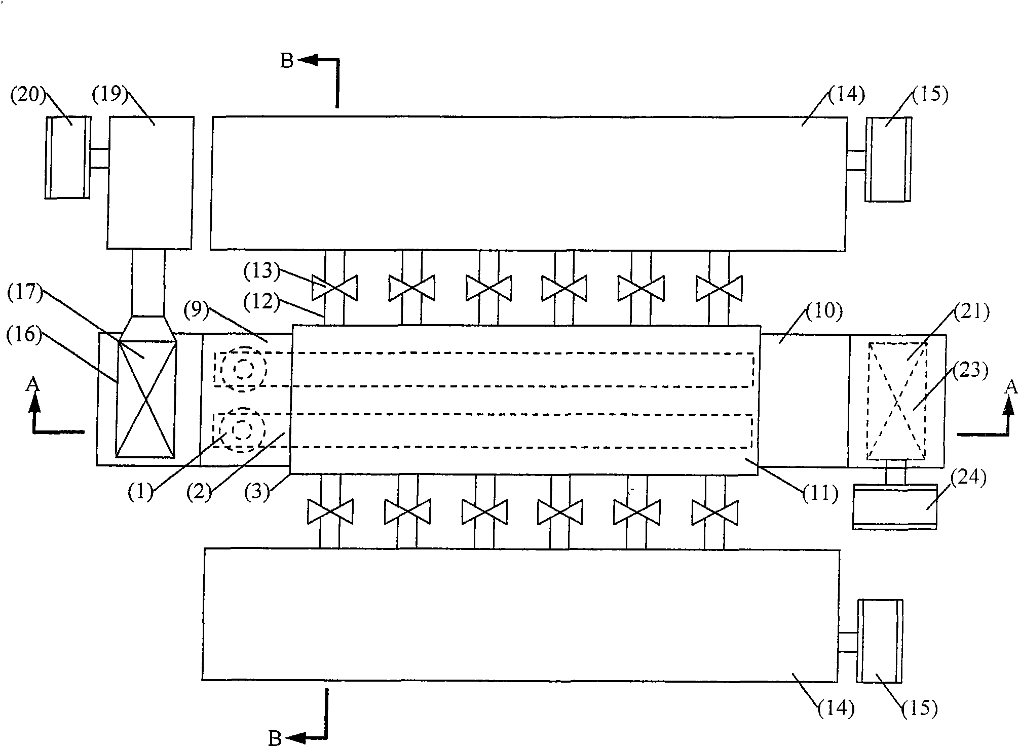
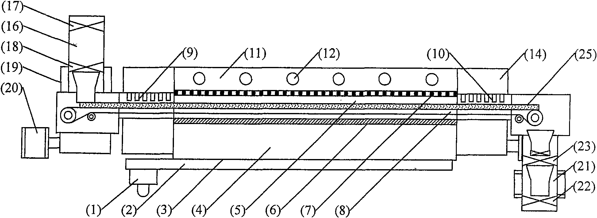
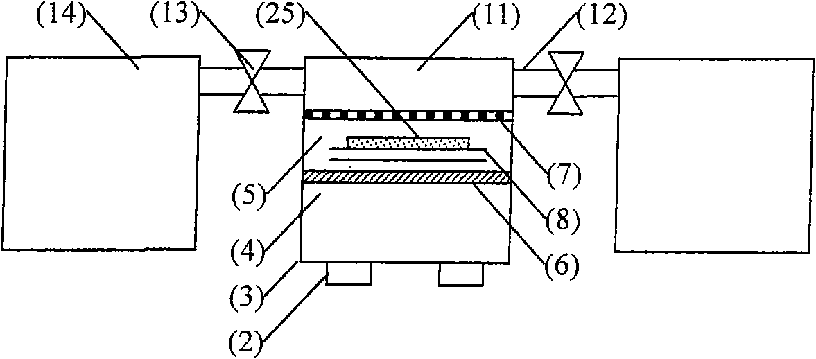
[0046] A microwave continuous freeze-drying system, comprising a microwave vacuum freeze-drying device, a vacuum water catcher, a vacuum feeding device, and a vacuum discharging device, wherein the microwave vacuum freeze-drying device includes a microwave generator 1, a microwave antenna 2, an atmospheric pressure microwave Cavity 4, vacuum microwave cavity 5, vacuum partition 6, porous air-permeable microwave shielding plate 7, low-loss conveyor belt 8, front-end vacuum microwave suppressor 9, rear-end vacuum microwave suppressor 10, characterized in that: freeze-dried in microwave vacuum The device is provided with a composite freeze-drying chamber 3 composed of an atmospheric microwave chamber 4 and a vacuum microwave chamber 5, and is separated by a microwave-permeable vacuum partition 6 between the atmospheric pressure microwave chamber 4 and the vacuum microwave chamber 5. The vacuum microwave cavity 5 is connected to the steam channel 11 of the vacuum water catcher, and...

Embodiment 2

[0059] Such as figure 1 , 2 , 3 form a set of microwave continuous freeze-drying system. It consists of a vacuum feeding device for vertical feeding, a microwave vacuum freeze-drying device, a vacuum discharging device, and a vacuum water-catching device.

[0060] The specific design of each part of this embodiment is as follows:

[0061] 1. Microwave generator 1 adopts four 915MHz, 75kW microwave sources, with a total power of 300kW;

[0062] 2. Microwave energy is fed into the atmospheric pressure microwave cavity 4 by the microwave antenna 2;

[0063] 3. The distance between the atmospheric pressure microwave cavity 4 and the vacuum partition 6 is 500 mm to make the microwave field more uniform;

[0064] 4. The low-loss conveyor belt 8 is made of PTFE-coated glass fiber belt, which can avoid the falling of materials and is suitable for processing small or granular materials;

[0065] 5. The steam channel 11 of the vacuum water catcher is located above the vacuum microw...

Embodiment 3

[0080] Such as figure 1 , 2 , 3, but change the vacuum feeding device to such as Figure 7 , 8 shown. The system consists of a vacuum feeding device for horizontal feeding, a microwave vacuum freeze-drying device, a vacuum discharging device, and a vacuum water trapping device.

[0081] The specific design of each part of this embodiment is as follows:

[0082] 1. Microwave generator 1 uses two 2450MHz, 30kW microwave sources, with a total power of 60kW;

[0083] 2. The distance between the atmospheric pressure microwave cavity 4 and the vacuum partition 6 is 200mm to make the microwave field more uniform;

[0084] 3. The cold trap 14 of the vacuum water catching device has a water catching capacity greater than or equal to 120kg / h

[0085] 4. The horizontal feeding vacuum chamber is adopted, which can conveniently input large bulk materials;

[0086] 5. Others are the same as in Example 1.

[0087] The system formed in this embodiment can be used to process a cube-sha...


PUM


Abstract

The invention discloses a continuous vacuum freeze-drying system using microwave energy as a heat source, belonging to the technical field of freeze-drying. The system comprises a microwave vacuum freeze-drying device, a vacuum water catching device, a vacuum feed device and a vacuum discharge device, wherein the microwave vacuum freeze-drying device is internally provided with a combined type freeze-drying cabin consisting of a normal-pressure microwave cavity and a vacuum microwave cavity, and the normal-pressure microwave cavity and the vacuum microwave cavity are partitioned by a microwave-transmitted vacuum partition board; the vacuum microwave cavity is connected with a steam channel of the vacuum water catching device; and the vacuum microwave cavity and the steam channel are partitioned by a porous ventilate microwave shielding board. The invention solves the problem of microwave disruptive discharge within a vacuum pressure range required by freeze-drying, has the advantages of good sealing property, high utilization ratio and high freeze-drying speed and can be used for effectively realizing the application of automatic industrialization.

Description

technical field [0001] The invention relates to a continuous vacuum freeze-drying system using microwave energy as a heat source, belonging to the technical field of freeze-drying. Background technique [0002] Vacuum freeze-drying (hereinafter referred to as freeze-drying) is carried out below zero degrees Celsius, even (-60)-(-70) degrees Celsius, and under the condition of vacuum anoxic. During the drying process, the chemical and biochemical reactions in the processed material (hereinafter referred to as the material) can be minimized; the volatilization of the ingredients can be reduced; there is basically no shrinkage and deformation after drying. Compared with ordinary drying methods, it can keep the original shape and composition of materials well. At present, freeze-drying is mainly used in fields such as medicine, food, biology, and chemical industry. [0003] Freeze-drying has experienced hundreds of years of development, and a second-generation freeze-drying eq...

Claims


Application Information

Patent Timeline
Patent Type & Authority Applications(China)
IPC IPC(8): F26B15/18F26B7/00
Inventor 周川刘毅刘朝辉杨涛姚波李兴化康琪游俊
Owner 周川
Why Eureka
Try Eureka