Non-contact measurement method for geometric parameters of optical part and measuring device thereof

A technology of non-contact measurement and optical parts, which is applied in the field of non-contact optical measurement of geometric quantities, and can solve problems such as slow speed, small dynamic range of measurement, and high cost.

Active Publication Date: 2010-12-22
西安波谱致航光电科技有限公司
View PDF8 Cites 12 Cited by
  • Summary
  • Abstract
  • Description
  • Claims
  • Application Information

AI Technical Summary

Problems solved by technology

[0003] The present invention provides a non-contact measuring device and a method for measuring thickness, moving distance and center height, so as to overcome the problems of slow speed, small dynamic range of measurement, high cost and unsuitability for on-line rapid measurement in the prior art

Method used


Image

  • Non-contact measurement method for geometric parameters of optical part and measuring device thereof
  • Non-contact measurement method for geometric parameters of optical part and measuring device thereof
  • Non-contact measurement method for geometric parameters of optical part and measuring device thereof

Examples


Embodiment 1

[0044] Example 1, see figure 2 and image 3 .

[0045] A non-contact measurement method for the thickness of an optical part. The optical switch drive 6 is controlled by the control and calculation unit 8 to drive the optical switch to form a transmission band 11 whose diameter decreases / increases successively, and the parallel light passing through the optical switch forms an annular band Parallel light, then the converging point after passing through the lens moves backward / forward sequentially along the optical axis direction, when the converging point is aimed at the upper and lower surfaces of the part, the optical path returns symmetrically to the original path, and energy peaks appear twice on the detector 9 , the two peaks appear one by one corresponding to the radius of different annular light bands, then the geometric thickness of the optical flat part to be tested is calculated according to the following formula:

[0046] d = ...

Embodiment 2

[0050] Example 2, see Figure 5 .

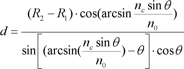
[0051] A non-contact measurement method for the moving distance of optical parts, through the control and calculation unit 8 to control the optical switch drive 6 to drive the optical switch to form a transmission zone 11 whose diameter is reduced / increased once, and the parallel light passing through the optical switch forms an annular zone shape parallel light, then the converging point after passing through the lens moves backward / forward in turn along the optical axis direction, aim at a surface of the part twice before and after the movement, record the energy change on the detector, and obtain the light band corresponding to the peak energy Radius, then the moving distance of the optical part 10 to be measured is:

[0052] d = ( R 2 - R 1 ) ...

Embodiment 3

[0054] Example 3, see Figure 6 .

[0055] A non-contact measurement method for the center height of an optical lens. The optical switch drive 6 is controlled by the control and calculation unit 8 to drive the optical switch to form a transmission band 11 whose diameter is reduced / increased once, and the parallel light passing through the optical switch forms a ring Strip parallel light, then the converging point after passing through the lens moves backward / forward in sequence along the optical axis. At a certain light band radius, after being focused by the axicon lens, the converging point is aimed at the front surface, the light path returns symmetrically, and an energy peak appears on the detector 9, record the radius R of the light band at this moment 1 , the radius of the light band continues to increase, and the converging point is far away from the optical system. When the light band passes through the front surface and just converges on the back surface, the light p...


PUM


Abstract

The invention belongs to the field of non-contact optical measurement of geometrical quantities, and particularly relates to a non-contact measurement method for geometric parameters of an optical part and a measuring device thereof. The invention aims to overcome the defects of low speed, small dynamic range for measurement, high cost and inapplicability to on-line quick measurement in the priorart. In order to overcome the defects, the technical scheme provided by the invention is a non-contact measurement method for geometric parameters of an optical part, which comprises the following steps: modulating the collimated light by using an electric scanning optical switch to form annular collimated light, converging the collimated light through an axicon lens (Fresnel lens) to realize convergent points at different distances, collimating by utilizing the convergent points and identifying the surface of the optical part, thereby measuring the geometrical thickness and motion distance of the optical part and the center height of the optical lens. The invention has the advantages of low cost, high stability, simple instrument structure and easy processing, is suitable for quick on-line measurement, and can realize wider dynamic measurement range compared with spectral scanning instruments.

Description

Technical field: [0001] The invention belongs to the field of non-contact optical measurement of geometric quantities, in particular to a non-contact measurement method of geometric parameters of optical parts and a measurement device thereof. Background technique: [0002] At present, the non-contact measurement methods of geometric parameters (thickness, center height, moving distance) of optical parts mainly include photometric type (mechanical scanning type) and spectral type. EP0248552A1 discloses a laser with oblique incidence to measure the thickness of flat transparent materials, and CN1132348A to improve its light deflection mechanism. This type of equipment is only used for the detection of the thickness of flat parts, and cannot detect flat, concave, convex, concave-convex. Such as optical parts and distance; JP5018716 (A) discloses a method for measuring the geometric thickness of parts based on scanning objective lens. Due to the application of mechanical scanni...

Claims


Application Information

Patent Timeline
Patent Type & Authority Applications(China)
IPC IPC(8): G01B11/02G01B11/06
Inventor 梁海锋刘缠牢
Owner 西安波谱致航光电科技有限公司
Why Eureka
Try Eureka