
Charging method applicable to super capacitor of wind generating set pitch control system

A technology for wind turbines and pitch systems, which is applied to systems and electrical components that store electrical energy, and can solve problems such as low charging efficiency.

Inactive Publication Date: 2010-12-22
XUJI GRP +1
View PDF3 Cites 5 Cited by
  • Summary
  • Abstract
  • Description
  • Claims
  • Application Information

AI Technical Summary

Problems solved by technology

[0006] The purpose of the present invention is to provide a charging method suitable for the supercapacitor of the pitch system of the wind power generating set, in order to solve the problem of low charging efficiency in the prior art

Method used


Image

  • Charging method applicable to super capacitor of wind generating set pitch control system
  • Charging method applicable to super capacitor of wind generating set pitch control system
  • Charging method applicable to super capacitor of wind generating set pitch control system

Examples


Embodiment Construction

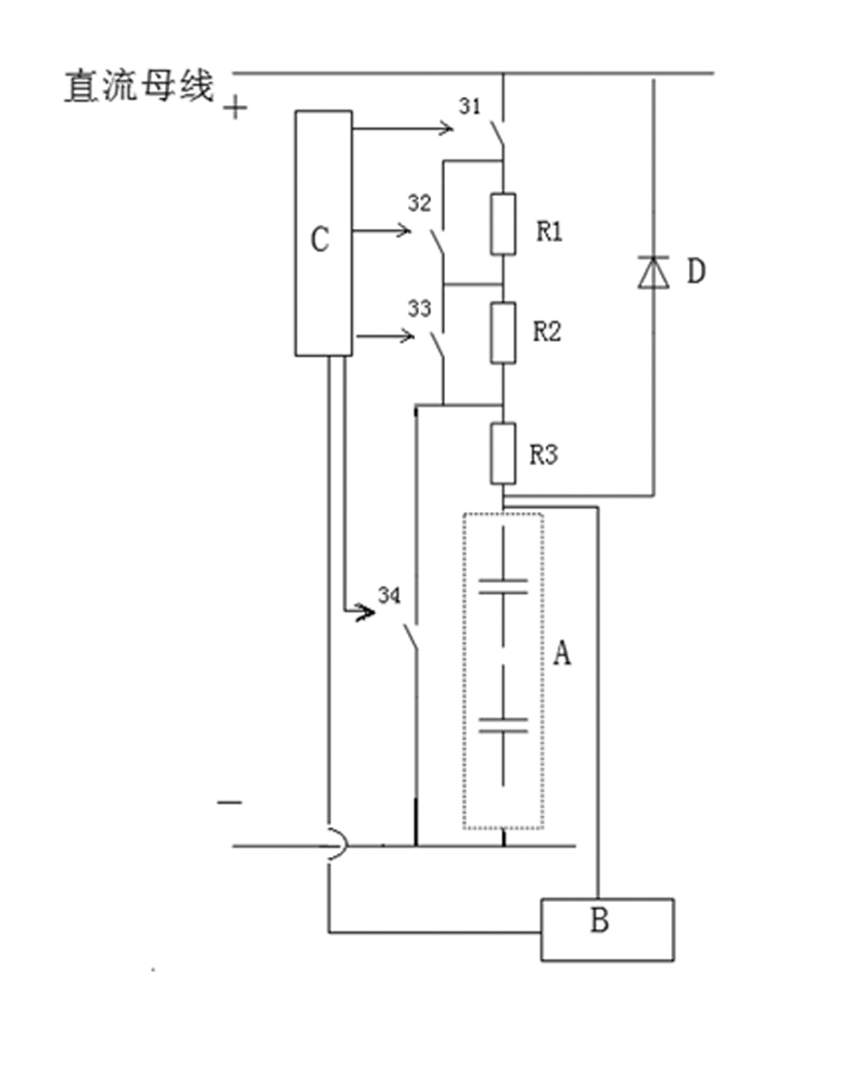
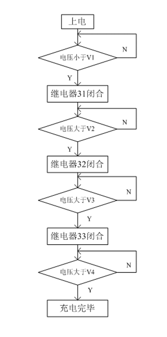
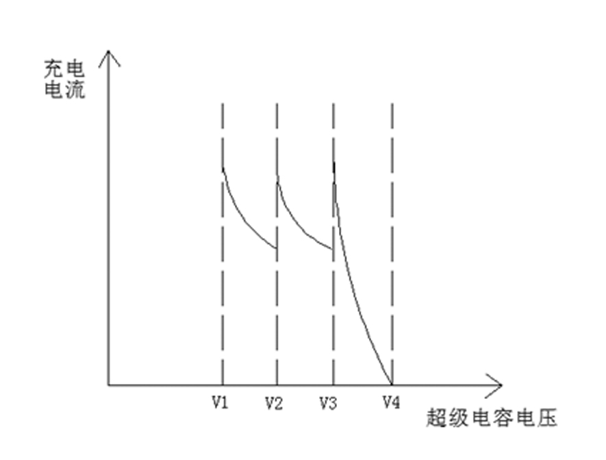
[0013] The main point of the method of the present invention is to increase the charging current by cutting off the resistance of the charging circuit during the process of the charging current decreasing continuously. The wind power variable pitch standby power system adopting the method of the present invention is as figure 1 As shown, the contacts of the charging relay 31, the first switching resistor R1, the second switching resistor R2, the power resistor R3, the supercapacitor bank A, the first switching resistor R1, Switching relay contacts (32, 33) are connected in parallel on the second switching resistor R2, and the power resistor R3 is a permanent resistor. The above three resistors and the relay contacts together constitute the charging circuit of the super capacitor bank; A discharge relay contact 34 is connected in parallel to the part of the capacitor bank connected in series. The power resistor R3 and the discharge relay contact 34 together form a discharge cir...


PUM


Abstract

The invention relates to a charging method applicable to a super capacitor of a wind generating set pitch control system, which comprises the following steps of: setting a starting valve value, a stopping valve value and at least one optimized charging valve value between the starting valve value and the stopping valve value; starting a charging branch circuit to charge when the terminal voltage of a super capacitor set is less than the starting valve value; increasing a charging current when the terminal voltage of the super capacitor set reaches a first optimized charging valve value, continuously charging until the terminal voltage of the super capacitor set reaches the stopping valve value if a second optimized charging valve value does not exist,, and increasing the charging current again until the terminal voltage of the super capacitor set reaches a final optimized charging valve value if the second optimized charging valve value exists; and increasing the charging current to continuously charge until the terminal voltage of the super capacitor set reaches the stopping valve value. The charging method has high efficiency.

Description

technical field [0001] The invention relates to a charging method for a backup power supply of a wind power generation pitch system. Background technique [0002] The pitch system, also known as the pitch system, refers to a system that changes the pitch angle of the blades through control technology to improve wind energy efficiency and obtain the best energy output. The grid voltage is the key to the stable operation of the pitch control system, and the grid voltage will lose power, drop and other phenomena. In order to prevent power loss or drop in voltage from the grid, the pitch system needs to be equipped with a backup power supply. When the power grid voltage is down, the backup power supply provides energy to the pitch system to support a series of operations such as pitch reset and fan shutdown, so that the pitch system can run stably for a period of time to ensure the safety of the fan. [0003] Backup power storage devices generally use batteries and supercapaci...

Claims


Application Information

Patent Timeline
IPC IPC(8): H02J15/00
Inventor 陶学军赵瑞杰李朝锋张举良刘德林胡剑生杨银锴初永刚
Owner XUJI GRP
Learn More