Eureka AIR delivers breakthrough ideas for toughest innovation challenges, trusted by R&D personnel around the world.

Flat-plate heat pipe

A flat heat pipe and plate technology, applied in indirect heat exchangers, lighting and heating equipment, etc., can solve the problems of reduced condensation area, reduced heat transfer capacity, complex structure, etc., to reduce the generation of non-condensable gas, manufacture The effect of simple process and simple and compact structure

Inactive Publication Date: 2010-12-29
SHANDONG UNIV
View PDF11 Cites 15 Cited by
  • Summary
  • Abstract
  • Description
  • Claims
  • Application Information

AI Technical Summary

Problems solved by technology

When the heat pipe is working, the generated gas flows to the condensation section and gathers to form an air lock, so that the effective condensation area is reduced, the thermal resistance is increased, the heat transfer performance is deteriorated, and the heat transfer capacity is reduced or even fails.
[0006] (2) Deterioration of the physical properties of the working medium
However, the above-mentioned "Platform Loop Heat Pipe (1)" has the problems of complex structure, poor reliability, and inability to effectively disperse non-condensable gases.

Method used


Image

  • Flat-plate heat pipe
  • Flat-plate heat pipe
  • Flat-plate heat pipe

Examples


Embodiment Construction

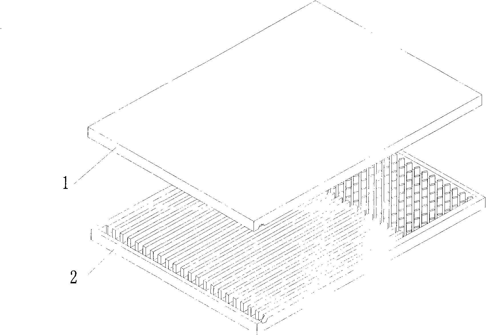
[0022] figure 1 An exploded view of the structure of the flat heat pipe of the present invention is given. The flat heat pipe of the present invention is formed by fastening the upper plate 1 and the lower plate 2 up and down. The materials of the upper plate 1 and the lower plate 2 are stainless steel, copper or high thermal conductivity materials such as aluminum. The connection methods used can be welding, clamping, bonding, etc., and the welding method is brazing, that is, using a filler metal with a melting point lower than the melting point of the base metal at a temperature lower than the melting point of the base metal and higher than the melting point of the solder , using liquid solder to wet and spread on the surface of the base metal and fill in the gap between the base metal, dissolve and diffuse with the base metal, and realize the welding of the connection between the parts. During welding, the solder melts but the base metal does not. The structures of the up...


PUM


Abstract

The invention provides a flat-plate heat pipe. The flat-plate heat pipe comprises an upper sheet and a lower sheet, wherein the upper sheet and the lower sheet are buckled together to form a complete heat pipe; the structures of the upper sheet and the lower sheet are symmetrical to each other and both comprise an evaporation area, an insulation area and a condensation area which are distributed in turn; the evaporation area and the insulation area are connected integrally; the condensation area and the insulation area are obviously separated and communicated with each other; a liquid charging port for charging a working medium is formed in the evaporation area; parallel grooves are formed in the evaporation area and the insulation area and pass through the evaporation area and the insulation area; the ends of the grooves in the evaporation area are communicated with each other, and the other ends of the grooves in the insulation area are communicated with the condensation area; fin columns are distributed in the condensation area; and an air outlet is formed on the edge of one side of the condensation area for vacuumizing during encapsulation or releasing non-condensable gas as necessary. The flat-plate heat pipe has the advantages of large heat transfer amount, high temperature evenness performance, high reliability and simple manufacturing process, and can effectively disperse the non-condensable gas and reduce generation of the non-condensable gas on the basis of ensuring the heat transfer performance.

Description

technical field [0001] The invention relates to a flat heat pipe, which belongs to the technical field of flat heat dissipation. Background technique [0002] The heat pipe was developed in the 1960s. It uses the latent heat of the phase change of the working medium for heat transfer and has a high unidirectional thermal conductivity. With the development of higher heat transfer performance and miniaturization of heat pipes, the improvement of flat heat pipes as heat transfer pipes has become a hot technology in the research and development of heat pipes. [0003] Flat heat pipes are light in weight, flexible in structure, have extremely high thermal conductivity and good isothermal performance, and are widely used in the cooling of electronic devices and thermal control systems of space technology. An important factor in the heat transfer capability of a heat pipe. [0004] According to the structure, heat pipes can be divided into: ordinary heat pipes, separated heat pip...

Claims


Application Information

Patent Timeline
IPC IPC(8): F28D15/02F28D15/04
Inventor 张树生陈雅群郭雷
Owner SHANDONG UNIV
Why Eureka
Eureka Blog
Learn More