Optical fiber current sensor and manufacturing method thereof

An optical fiber current and manufacturing method technology, applied in voltage/current isolation, measuring current/voltage, instruments, etc., can solve the problems of complex insulation structure, large volume and weight, rising insulation cost, etc., and achieve a large dynamic measurement range and frequency. The effect of wide response range and simple insulation structure

Active Publication Date: 2010-12-29
XIAN SINO HUAXIN MEASUREMENT & CONTROL
View PDF0 Cites 16 Cited by
  • Summary
  • Abstract
  • Description
  • Claims
  • Application Information

AI Technical Summary

Problems solved by technology

[0005] The electromagnetic current sensor is mainly composed of iron core, transformer oil, copper wire and insulating medium. The volume and weight of these materials are large, and as the voltage level increases, the insulation structure becomes more and more complicated. Type current sensors are bulky and expensive
[0006] 2. There are problems of magnetic saturation and ferromagnetic resonance
[0007] Using the principle of electromagnetic induction, using the iron core structure, when the measured current increases abnormally, the sensor core will be magnetically saturated, which will seriously reduce the measurement accuracy
[0008] 3. The insulation structure is complicated and the cost is high
[0009] Due to the poor insulation of the design structure, relying on oil insulation, gas insulation and other insulation methods, as the voltage level increases, the insu

Method used


Image

  • Optical fiber current sensor and manufacturing method thereof
  • Optical fiber current sensor and manufacturing method thereof
  • Optical fiber current sensor and manufacturing method thereof

Examples


Example Embodiment

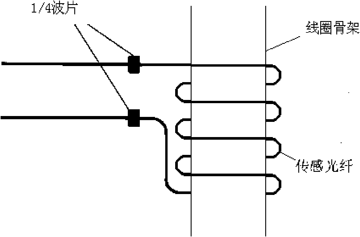
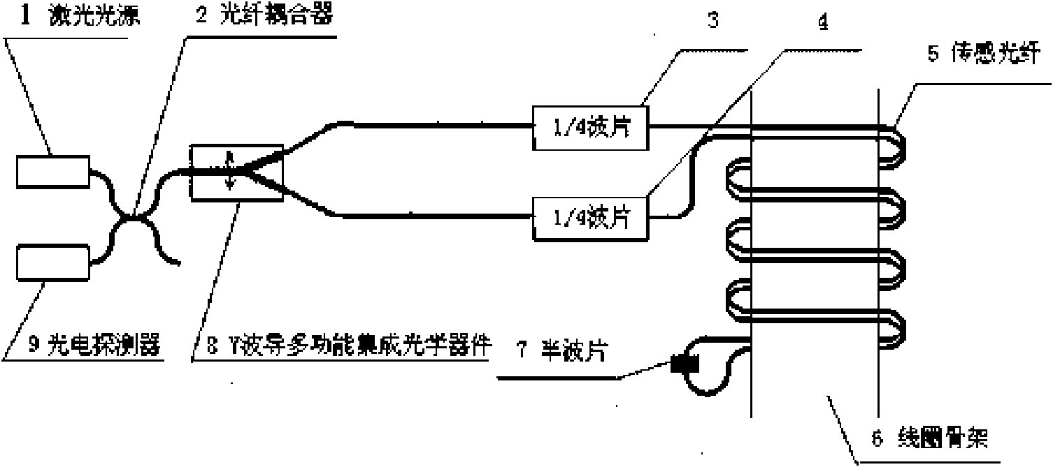
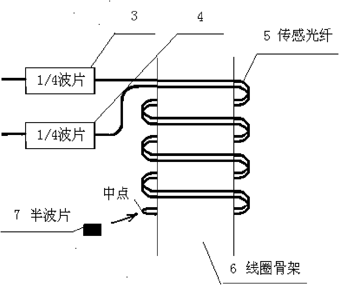
[0040] See figure 2 , The present invention provides a fiber optic current sensor, including a first quarter wave plate 3, a second quarter wave plate 4, a half wave plate 7, a sensing fiber 5 and a coil bobbin 6; The one-wave plate 3 and the second quarter-wave plate 4 are connected by a sensing fiber 5, and the middle of the sensing fiber 5 is coupled with a half-wave plate 7; the sensing fiber 5 is double-wire wound on the coil frame 6 in the same direction on.

[0041] The optical fiber current sensor provided by the present invention also includes a laser light source 1, a photodetector 9, a fiber coupler 2, a Y-waveguide multifunctional integrated optical device 8. The Y-waveguide multifunctional integrated optical device 8 can also adopt several separate devices. Composition, such as: polarizer, fiber coupler and phase modulator together to realize the function of Y-waveguide multifunctional integrated optical device; laser light source 1 and photodetector 9 are combined ...


PUM


Abstract

The invention relates to an optical fiber current sensor and a manufacturing method thereof. The optical fiber current sensor comprises a first quarter wave plate, a second quarter wave plate, a sensing optical fiber and a coil frame, wherein the first quarter wave plate and the second quarter wave plate are communicated through the sensing optical fiber; the sensing optical fiber is coupled with a half-wave plate; and double wires of the sensing optical fiber double wire are wound on the coil frame in the same direction. The invention provides an optical fiber current sensor which has the advantages of high precision, small volume, light weight and no sensitivity to vibration or rotation due to no Sagnac effect and a manufacturing method thereof.

Description

technical field [0001] The invention relates to a current sensor and a manufacturing method thereof, in particular to an optical fiber current sensor and a manufacturing method thereof. Background technique [0002] With the continuous improvement of the voltage level and capacity of the power grid in the power system, the requirements for current sensors are getting higher and higher. Traditional electromagnetic current sensors have gradually exposed serious defects and cannot meet the needs of high-voltage and ultra-high-voltage power grids. In addition to the traditional electromagnetic current sensor, there is currently a Sagnac fiber optic current sensor (see figure 1 ) is in the research and development stage, and has attracted much attention as a possible replacement product of the traditional ferromagnetic current sensor, but this Sagnac-type fiber optic current sensor has not entered the stage of practical application. Because this Sagnac-type fiber optic current s...

Claims


Application Information

Patent Timeline
IPC IPC(8): G01R15/24G01R19/00G02B6/34
Inventor 徐金涛赵卫
Owner XIAN SINO HUAXIN MEASUREMENT & CONTROL
Why Eureka
Try Eureka