Image denoising method based on visual non-classical receptive field model
A non-classical receptive field and visual technology, applied in the field of image processing, can solve the problem of the decline of the response curve, and achieve the effect of retaining details
- Summary
- Abstract
- Description
- Claims
- Application Information
AI Technical Summary
Problems solved by technology
Method used
Image
Examples
Embodiment approach 1
[0048] Embodiment 1—Processing the simulated ladder image with Gaussian noise added
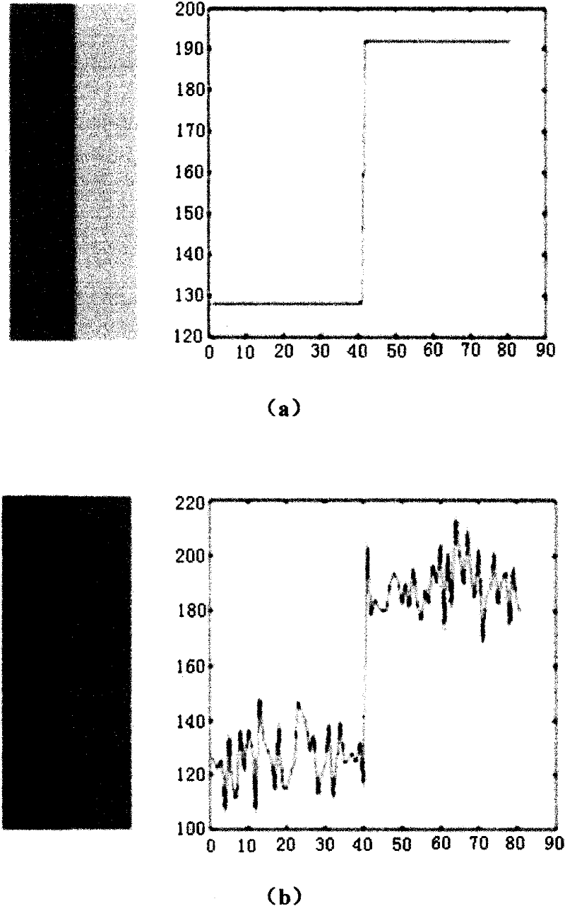
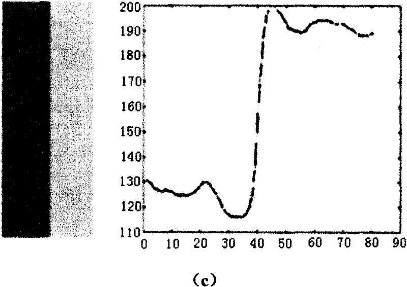
[0049] Figure 5 (a) is the original ladder image, Figure 5 (b) is a ladder image with Gaussian white noise (σ=10), and the right image is the pixel grayscale image of the horizontal center line of the image. We set the model parameters as d c = 3, d r = 10, d u = 3, A c = 1.0, A r =1,0,A u =1.0, then the image processed according to the detailed technical scheme of the present invention is shown in Figure 5 (c), it can be seen that due to the expansion of the receptive field size in the low-contrast area, the high-frequency noise is significantly reduced. At the same time, in the high-frequency area such as the edge of the step, the edge is preserved and enhanced due to the contraction of the receptive field caused by high contrast (Mach effect ).
specific Embodiment approach 2
[0050] Specific implementation mode two - filtering natural images with Gaussian noise, salt and pepper noise and taint noise added
[0051] The present invention is used to denoise a group of natural images added with Gaussian self-noise, salt-and-pepper noise and stain noise, wherein the noise intensity is σ=30. The diameter of the receptive field is the parameter corresponding to the data in bold in Table 1 to Table 3, and the sensitivity of the central area, peripheral area and sub-area of the receptive field is 1.0. Tables 1 to 3 show the peak-to-peak signal-to-noise ratios of Gaussian white noise, salt and pepper noise, and stain noise before and after filtering of the output image processed according to the detailed technical solution of the present invention. PSNR1 represents the peak-to-peak signal-to-noise ratio of the polluted image, and PSNR2 represents the peak-to-peak signal-to-noise ratio of the filtered image is given in the table header. It can be seen from...
PUM
 Abstract
Description
Claims
Application Information
 - R&D
- Intellectual Property
- Life Sciences
- Materials
- Tech Scout
- Unparalleled Data Quality
- Higher Quality Content
- 60% Fewer Hallucinations
Browse by: Latest US Patents, China's latest patents, Technical Efficacy Thesaurus, Application Domain, Technology Topic, Popular Technical Reports.
© 2025 PatSnap. All rights reserved.Legal|Privacy policy|Modern Slavery Act Transparency Statement|Sitemap|About US| Contact US: help@patsnap.com


