Identification and compensation method of servo system disturbance moment

A servo system and interference torque technology, applied in control systems, vector control systems, DC motor speed/torque control, etc., can solve problems such as difficulty in establishing friction models, low interference torque accuracy, and difficulty in estimating interference torque.

Inactive Publication Date: 2012-11-21
BEIJING INSTITUTE OF TECHNOLOGYGY
View PDF0 Cites 0 Cited by
  • Summary
  • Abstract
  • Description
  • Claims
  • Application Information

AI Technical Summary

Problems solved by technology

[0006] First, the disturbance torque is not easy to be estimated by the CMAC network and the accuracy of the estimated friction and other disturbance torque is not high, it is difficult to realize accurate compensation for the servo system and reduce the precision of the servo system
[0007] Second, the establishment of the friction model is relatively difficult. Therefore, it is more difficult to use the friction model to identify the disturbance torque of the servo system

Method used


Image

  • Identification and compensation method of servo system disturbance moment
  • Identification and compensation method of servo system disturbance moment
  • Identification and compensation method of servo system disturbance moment

Examples


Embodiment 1

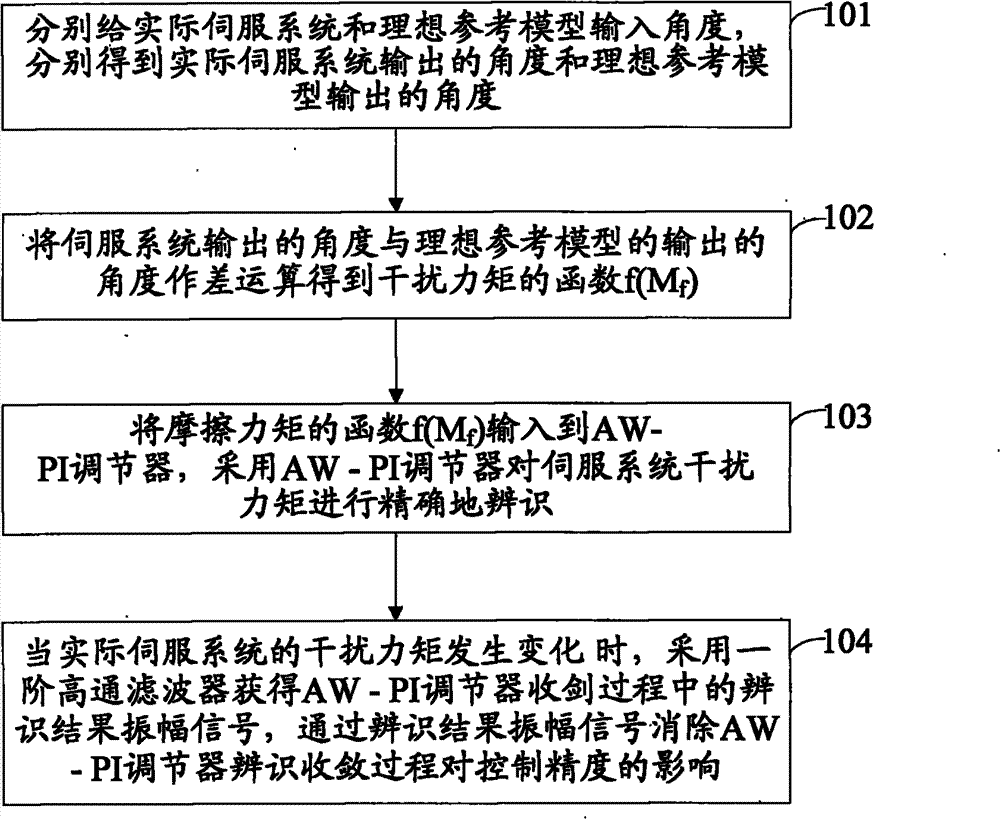
[0027] Such as figure 1 As shown, the embodiment of the present invention provides a servo system disturbance torque identification method, the method steps are as follows:

[0028] Step 101: Input the angle θ for the actual servo system and the ideal reference model respectively r (s), get the angle θ(s) output by the actual servo system and the angle output by the ideal reference model respectively

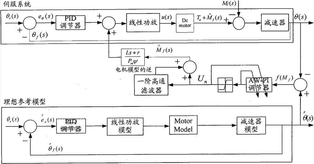
[0029] Among them, such as figure 2 As shown, the angle θ r (s) are respectively input into the actual servo system and the ideal reference model. There are disturbance torques in the actual servo system, which will reduce the accuracy of the servo system, while the ideal reference model is a servo system model with high precision and no disturbance torque. Therefore, the actual The angle θ(s) output by the servo system and the angle output by the ideal reference model There is bound to be a discrepancy between them.

[0030] Among them, the disturbance torque is the fr...

Embodiment 2

[0054] Such as Figure 5 As shown, the embodiment of the present invention provides a method for compensating the disturbance torque identified in embodiment 1, including:

[0055] Step 201: The identified disturbance torque Multiply with the coefficient of the inverse motor model, and add the obtained value to the voltage signal u(s) of the actual servo system to obtain the compensated voltage signal;

[0056] Among them, the coefficients of the inverse motor model are Among them, Ls, r, P m and ψ are parameters of the inverse motor model, and each parameter value is determined by the model.

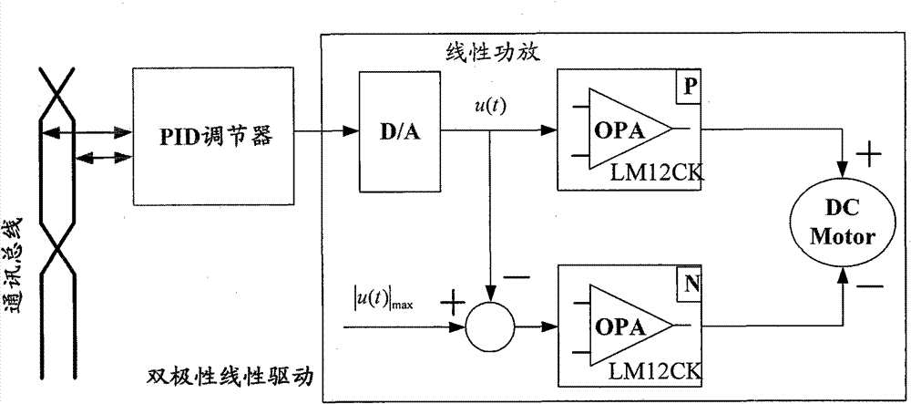
[0057] Step 202: Input the compensated voltage signal into the DC motor of the actual servo system to drive the DC motor to output torque

[0058] Among them, the coefficient of the compensated voltage signal and the DC motor Multiplied together, the output torque of the DC motor is

[0059] Among them, the compensated voltage signal obtained by multiplying the identified d...


PUM


Abstract

The invention discloses an identification and compensation method of a servo system disturbance moment, belonging to the technical field of mechanical manufacture and automation. The identification method comprises the following steps: inputting angles to an actual servo system and an ideal reference model to respectively obtain an angle output by the actual servo system and an angle output by the ideal reference model; performing subtracting operation on the angle output by the actual servo system and the angle output by the ideal reference model to obtain a function of the disturbance moment; outputting the function of the disturbance moment to an AW-PI regulator and identifying the disturbance moment of the actual servo system by the AW-PI regulator; and when the disturbance moment of the actual servo system changes, adopting an order highpass filter to obtain an identification result amplitude signal in the convergence process of the AW-PI regulator and utilizing the identification result amplitude signal to eliminate the influence of the convergence process of the AW-PI regulator to the disturbance moment. The invention improves the accuracy of the servo system and reduces the difficulty for identifying the disturbance moment.

Description

technical field [0001] The invention relates to the technical field of mechanical manufacturing automation, in particular to a method for identifying and compensating the disturbance torque of a servo system. Background technique [0002] With the development of our country's industry, people pay great attention to the development of the servo system, and at the same time put forward higher and higher requirements for its performance. However, the existence of the disturbance torque in the servo system limits the improvement of the performance of the servo system. How to eliminate the adverse effect of the disturbance torque of the servo system to improve the servo precision has become a difficult problem for scientific researchers. At present, there are two methods to eliminate the disturbance torque of the servo system, including: [0003] First, the CMAC (ControlMobileAttenuationCode, control mobile attenuation code) network and compensation link are used to dynamically ...

Claims


Application Information

Patent Timeline
Patent Type & Authority Patents(China)
IPC IPC(8): H02P7/00H02P21/14
Inventor 蒋志宏李辉杨健何川
Owner BEIJING INSTITUTE OF TECHNOLOGYGY
Why Eureka
Try Eureka