High-power factor electronic ballast of high-intensity gas discharging lamp

A technology for electronic ballasts and gas discharge lamps, applied in electric light sources, electrical components, lighting devices, etc., can solve problems such as large reactive power loss, complex circuits, and poor reliability, and achieve low cost, simplified circuit structure, and reliable sex high effect

Inactive Publication Date: 2010-12-29
上海送吉机电有限公司
View PDF3 Cites 7 Cited by
  • Summary
  • Abstract
  • Description
  • Claims
  • Application Information

AI Technical Summary

Problems solved by technology

However, the power factor of traditional magnetic ballasts is very low, and the reactive power loss is huge, while the power factor of general electronic ballasts is not high (PF10%) At present, although some electronic ballasts use single-chip microcomputers for constant power control, there are many defects such as complex circuits, poor reliability and high prices.

Method used


Image

  • High-power factor electronic ballast of high-intensity gas discharging lamp
  • High-power factor electronic ballast of high-intensity gas discharging lamp
  • High-power factor electronic ballast of high-intensity gas discharging lamp

Examples


Embodiment Construction

[0009] The present invention will be further described below in conjunction with the accompanying drawings.

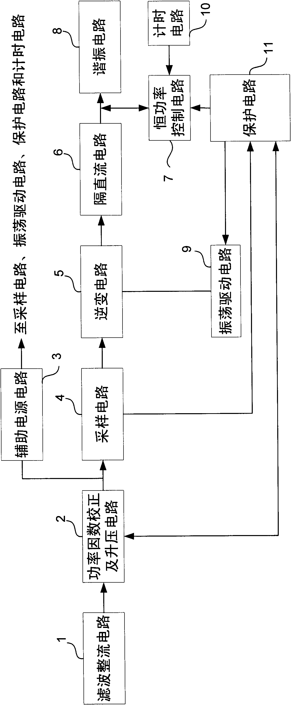
[0010] refer to figure 1 , the high power factor electronic ballast for high intensity gas discharge lamps of the present invention includes a filter rectifier circuit 1, a power factor correction and boost circuit 2, an auxiliary power supply circuit 3, a sampling circuit 4, an inverter circuit 5, and a constant power control circuit 7. Resonant circuit 8, oscillation drive circuit 9 and protection circuit 11. Wherein, the rectification and filtering circuit 1 is used for rectifying the input commercial power into pulsating direct current and smoothing and filtering. The power factor correction and boost circuit 2 is coupled to the output end of the filter rectifier circuit 1 for improving the power factor of the circuit. The auxiliary power supply circuit 3 is connected with the power factor correction and boost circuit 2, and is used to provide DC power to the sam...


PUM


Abstract

The invention discloses a high-power factor electronic ballast of a high-intensity gas discharging lamp, comprising a filtering rectifying circuit, a power factor correction and booster circuit, an auxiliary power source circuit, a sampling circuit, an inversion circuit, an oscillation drive circuit, a constant power control circuit, a resonant circuit and a protection circuit. A sampling circuitcollects an output voltage signal of the power factor correction and booster circuit and a current signal of the high-intensity gas discharging lamp; the inversion circuit is coupled with a first output end of the sampling circuit; the constant power control circuit comprises a magnet amplifier, a magnet amplifier control circuit and a power supply circuit; a primary winding of the magnet amplifier is connected in series with the resonant circuit; and one end of a control winding is coupled with the magnet amplifier control circuit, while the other end is coupled with the power supply circuit; the magnet amplifier control circuit controls the current flowing by the control winding to change in inverse proportion to the lamp current according to a control electric signal which is in positive proportion to the sampling lamp current and is output by a second output end of the sampling circuit. The invention simplifies the circuit structure and has low cost.

Description

technical field [0001] The invention relates to an electronic ballast for a high-intensity gas discharge lamp. Background technique [0002] High-intensity gas discharge lamps have many advantages such as high luminous efficiency, long life, high power, and low price. They are especially suitable for stations, docks, squares, road traffic, etc. Optimal electric light source for area lighting. However, the power factor of traditional magnetic ballasts is very low, and the reactive power loss is huge, while the power factor of general electronic ballasts is not high (PF<0.98), and the harmonic content (THD) also exceeds the standard (THD>10%) , although some electronic ballasts use single-chip microcomputers for constant power control, there are many defects such as complex circuits, poor reliability and high prices. Contents of the invention [0003] The technical problem to be solved by the present invention is to provide an electronic ballast with simple circuit, ...

Claims


Application Information

Patent Timeline
Patent Type & Authority Applications(China)
IPC IPC(8): H05B41/288H05B41/36
Inventor 冯关兴
Owner 上海送吉机电有限公司
Why Eureka
Try Eureka