Seawater source heat pump system

A source heat pump, seawater technology, applied in the energy field, to achieve the effect of large heat transfer coefficient outside the tube, improve operating efficiency, and reduce initial investment

Inactive Publication Date: 2011-01-05
青岛科创蓝新能源股份有限公司
View PDF7 Cites 11 Cited by
  • Summary
  • Abstract
  • Description
  • Claims
  • Application Information

AI Technical Summary

Problems solved by technology

[0011] The purpose of the present invention is to provide a seawater source heat pump system, which can effectively solve the problems of anti-corrosion, anti-algae, anti-b

Method used


Image

  • Seawater source heat pump system
  • Seawater source heat pump system
  • Seawater source heat pump system

Examples


specific Embodiment approach 1

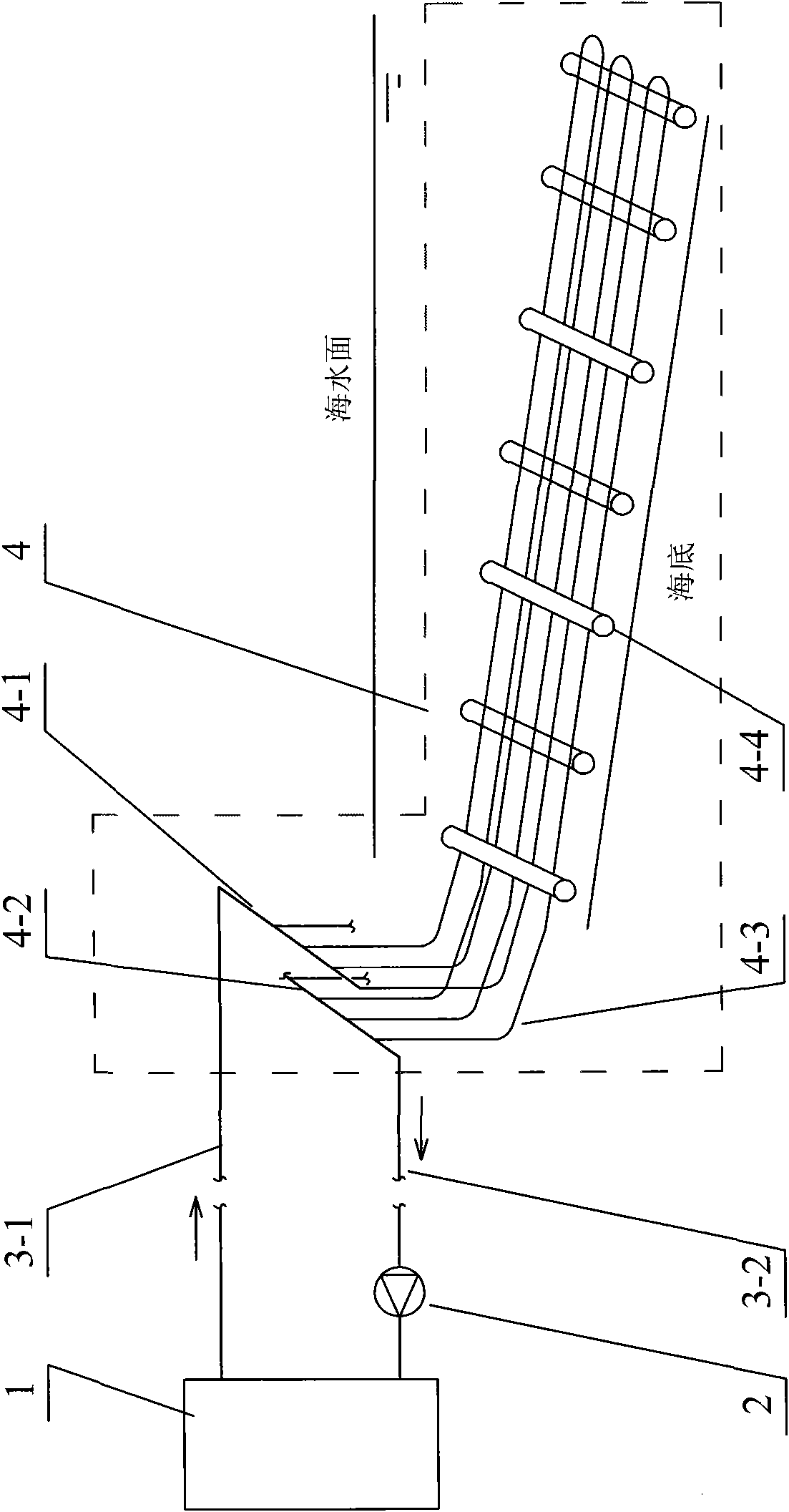
[0028] Specific implementation mode one (see figure 1 ), this embodiment is composed of heat pump unit 1, medium circulating water pump 2, medium water supply pipeline 3-1, medium return water pipeline 3-2 and long straight plastic pipe heat exchange device 4, medium water supply pipeline 3-1 and heat pump unit 1 It is connected with the water distribution pipe 4-1 of the long straight plastic pipe heat exchange device 4, the medium return water pipeline 3-2 is connected with the heat pump unit 1 and the water collection pipe 4-2 of the long straight plastic pipe heat exchange device 4, and the medium circulating water pump 2 is connected On the medium return line 3-2, the long straight plastic pipe heat exchange device 4 is composed of a water distribution pipe 4-1, a water collection pipe 4-2, a long straight engineering heat-conducting plastic pipe 4-3, and a weight 4-4. The heat-conducting plastic pipe 4-3 of the long straight project is laid back and forth along the deep ...

specific Embodiment approach 2

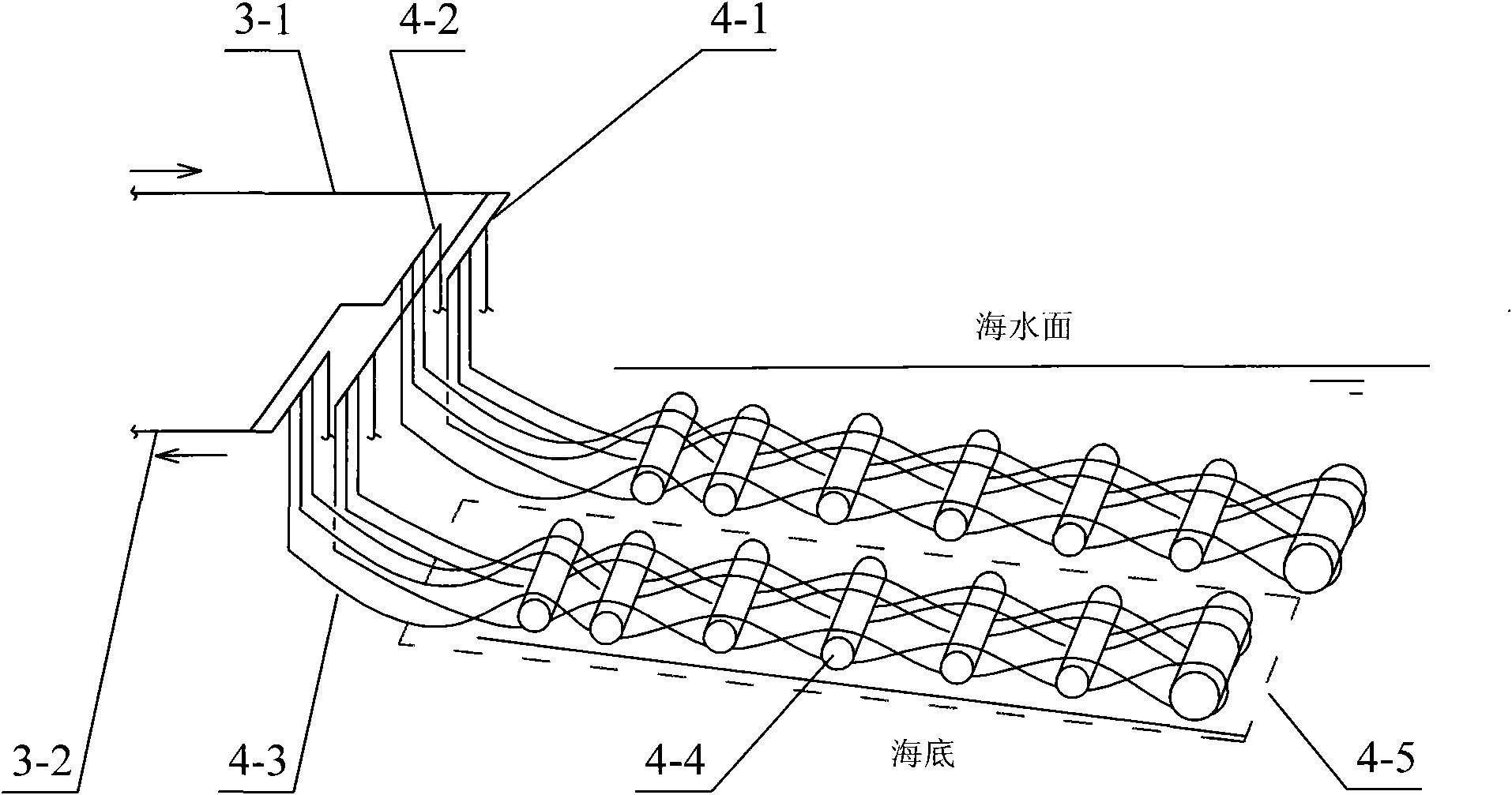
[0029] Specific implementation mode two (see figure 2 ), several long straight engineering heat-conducting plastic pipes 4-3 in the long straight plastic pipe heat exchange device 4 of the present embodiment are laid back and forth side by side in the horizontal direction to form a pipe row unit bundle 4-5, and a pipe row unit bundle 4-5 Then connect with water distribution pipe 4-1 and water collection pipe 4-2, a plurality of water distribution pipes 4-1 and water collection pipe 4-2 connect a plurality of pipe row unit tube bundles 4-5 in parallel, and weighting objects 4-4 are dispersedly arranged on the pipes On the row unit tube bundles 4-5, other composition and connection relations are the same as the specific embodiment one.

specific Embodiment approach 3

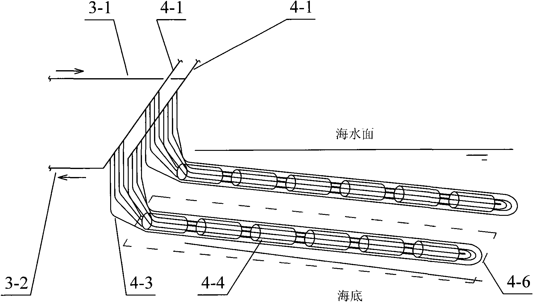
[0030] Specific implementation mode three (see image 3 ), several long straight engineering heat-conducting plastic pipes 4-3 in the long straight plastic pipe heat exchange device 4 of the present embodiment are bundled on the weight 4-4 to form a long dragon unit tube bundle 4-6, and a long dragon unit tube bundle 4-6 Connect with the water distribution pipe 4-1 and the water collection pipe 4-2 again, and a plurality of water distribution pipes 4-1 and the water collection pipe 4-2 connect a plurality of long dragon unit tube bundles 4-6 in parallel, and other composition and connection relations are the same as the specific embodiment one .


PUM

PropertyMeasurementUnit
Diameteraaaaaaaaaa
Lengthaaaaaaaaaa
Lengthaaaaaaaaaa

Abstract

The invention provides a seawater source heat pump system, relates to a system for extracting cold and heat energy from seawater by heat pump technology, and belongs to the technical field of energy. The invention aims to effectively solve the problems of corrosion prevention, algae prevention, organism prevention, scale prevention, control of conveying energy consumption of a water pump and the like of a seawater source. The system mainly comprises a heat pump machine set, a medium circulation water pump, a medium water supply pipeline, a medium water-returning pipeline and a long straight plastic pipe heat exchange device, wherein the long straight plastic pipe heat exchange device is formed by laying engineering thermally conductive plastic pipes in and fro in a long and straight way along the direction of deep sea, and is sunk to the bottom of the sea; the medium absorbs the cold and heat energy of the seawater at a long distance in the process of flowing in the pipes in and fro; and the heat pump machine set extracts the cold and heat energy from the medium. The seawater source heat pump system of the invention can extract the cold and heat energy of the seawater at the long distance from the deep sea.

Description

technical field [0001] The invention relates to a system for extracting cold and heat in seawater by using heat pump technology, which belongs to the field of energy technology. Background technique [0002] Using heat pump technology to extract cold heat from low-grade, renewable clean energy for heating and air conditioning of buildings is one of the effective ways to save energy and reduce emissions in buildings. These cold and heat sources include: seawater, groundwater, soil, urban sewage, etc. Their temperature is between 0 and 20°C in winter. When they are used as cold and heat sources of heat pumps, the primary energy of the heat pump system (coal, The utilization efficiency of oil and natural gas can reach 133% or even higher, and the energy saving range can be more than 45%. But when using these cold and hot energy sources, in addition to using them according to local conditions, some key problems need to be solved due to their own characteristics. [0003] The k...

Claims


Application Information

Patent Timeline
IPC IPC(8): F25B30/06F28F21/06
Inventor 吴荣华迟芳
Owner 青岛科创蓝新能源股份有限公司
Why Eureka
Try Eureka