
Phase frequency detector (PFD), phase frequency detection method thereof, phase locking loop (PLL) and frequency synthesizer

A frequency discriminator, phase-locked loop technology, applied in the field of frequency discriminator, phase discriminator, frequency synthesizer, frequency discriminator and phase discriminator, phase-locked loop field, can solve the deterioration of phase noise and spurious and other problems to achieve the effect of improving in-band phase noise and spurious

Inactive Publication Date: 2011-01-05
SHANGHAI NATLINEAR ELECTRONICS CO LTD
View PDF3 Cites 18 Cited by
  • Summary
  • Abstract
  • Description
  • Claims
  • Application Information

AI Technical Summary

Problems solved by technology

[0009] In fractional PLLs with delta-sigma modulators, such nonlinearity is not acceptable because it leads to degraded phase noise and spurious

Method used


Image

  • Phase frequency detector (PFD), phase frequency detection method thereof, phase locking loop (PLL) and frequency synthesizer
  • Phase frequency detector (PFD), phase frequency detection method thereof, phase locking loop (PLL) and frequency synthesizer
  • Phase frequency detector (PFD), phase frequency detection method thereof, phase locking loop (PLL) and frequency synthesizer

Examples


Embodiment 1

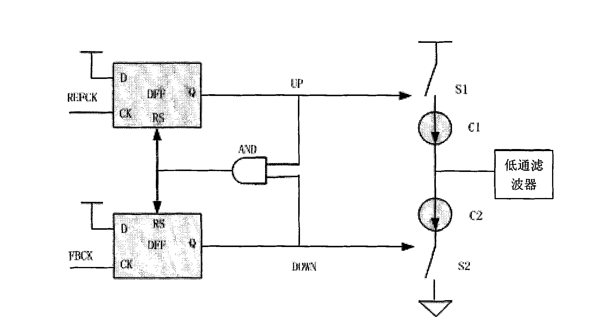
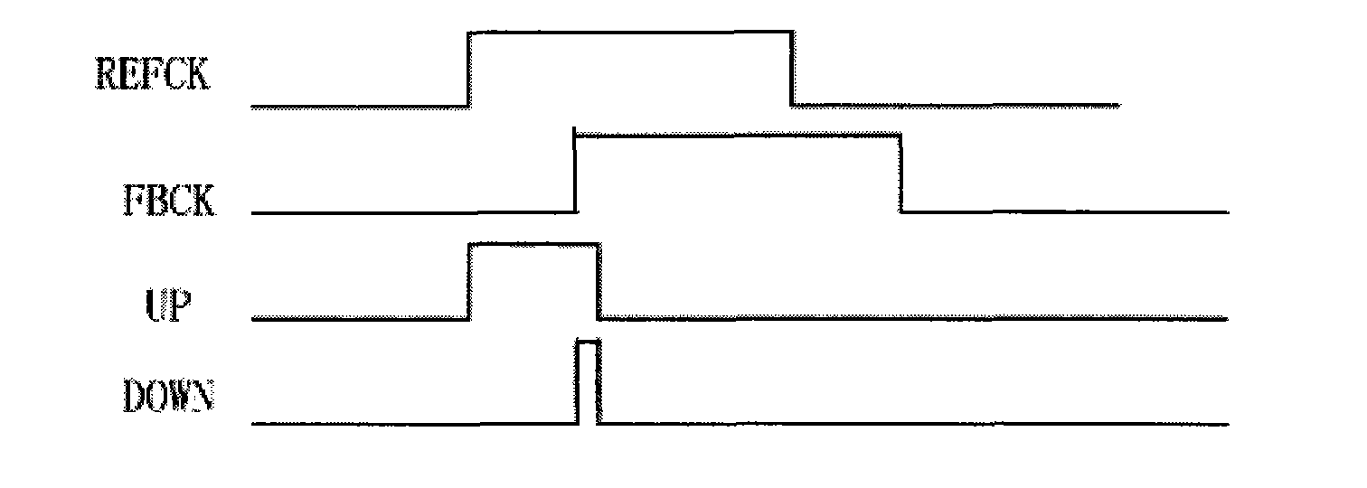
[0046] see Figure 7 , the present invention discloses a frequency and phase detector, and the frequency and phase detector is used for comparing the phases of a reference clock and a frequency divider feedback clock. When the phase of the feedback clock lagged behind the phase of the reference clock, the frequency detector phase detector output was used to increase the frequency of the pulse signal UP signal; when the phase of the feedback clock exceeded the phase of the reference clock, the frequency detector phase detector output used It is used to reduce the frequency of the pulse signal DOWN signal. The phase frequency detector includes two resettable DFFs; when both the UP signal and the DOWN signal are high, at least one of the two DFFs is delayed so that the two DFFs are reset; thus, when the PLL is at When locked, the frequency and phase detector works in the linear region.

[0047] Correspondingly, the frequency and phase detector further includes at least one dela...

Embodiment 2

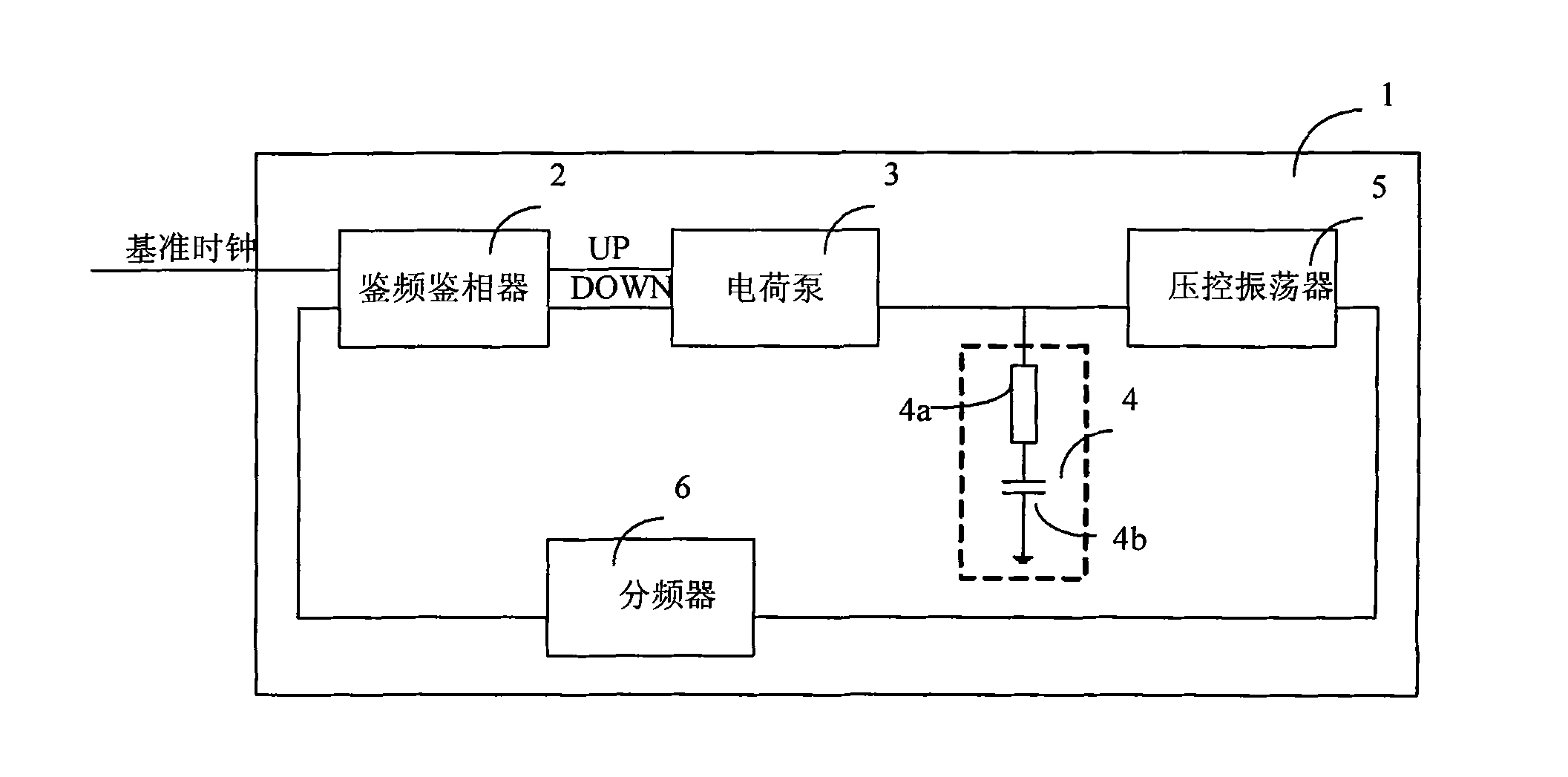
[0056] This embodiment discloses a phase-locked loop including the frequency and phase detector described in Embodiment 1. At the same time, this embodiment further improves the above-mentioned phase-locked loop. The improved phase-locked loop is as follows Figure 5 shown.

[0057] see Figure 5 , Figure 6 , the present invention discloses a phase-locked loop, the phase-locked loop includes a reference clock frequency divider 11, a frequency and phase detector 12, a charge pump 13, a low-pass filter 14, a voltage-controlled oscillator 15, and a divider connected in sequence. A frequency divider 16; the voltage-controlled oscillator 15 is connected with an AFC automatic frequency controller 17, and the frequency divider 16 is connected with a ΔΣ modulator 18.

[0058] read on Figure 5 , the crystal oscillator clock first passes through a reference clock divider to generate CKREF. The reference clock frequency divider 11 is a programmable frequency divider, and different ...


PUM


Abstract

The invention discloses a phase frequency detector (PFD) and a phase frequency detection method thereof. When the phase of a feedback clock lags behind the phase of a reference clock, a pulse signal UP signal for improving the frequency is output by the PFD; when the phase of the feedback clock exceeds the phase of the reference clock, a pulse signal DOWN signal for reducing the frequency is output by the PFD; the PFD comprises two DFFs (D Flip-flops) capable of resetting; when the UP signal and the DOWN signal are both high, at least one of the two DFFs is subjected to time delay so as to ensure that the two DFFs are reset; and when a PLL (Phase Locking Loop) is locked, the PFD works in a linear area. When the PLL is locked, the PFD works in the linear area, thus the invention can be used for improving the in-band phase noise and strays.

Description

technical field [0001] The invention belongs to the technical field of integrated circuit design, and relates to a phase-locked loop, in particular to a frequency and phase detector; at the same time, the invention also relates to a frequency and phase detector method for the frequency and phase detector; in addition, the invention also relates to A frequency synthesizer including the phase locked loop described above. Background technique [0002] At present, a Phase Locked Loop (PPL, Phase Locked Loop) is widely used in various fields of integrated circuit design. Such as figure 1 As shown, the phase-locked loop circuit 1 generally includes a frequency and phase detector 2 , a charge pump 3 , a low-pass filter 4 , a voltage-controlled oscillator 5 and a frequency divider 6 . The frequency and phase detector 2 is used to compare the phases of the reference clock and the feedback clock from the frequency divider 6 . When the phase of the feedback clock from the frequency ...

Claims


Application Information

Patent Timeline
Patent Type & Authority Applications(China)
IPC IPC(8): H03L7/08H03L7/18
Inventor 孙晶缪卫明裘旭亚姜亚伟刘桂芝吴国平黄年亚蒋小强
Owner SHANGHAI NATLINEAR ELECTRONICS CO LTD
Features
  • Generate Ideas
  • Intellectual Property
  • Life Sciences
  • Materials
  • Tech Scout
  • Unparalleled Data Quality
  • Higher Quality Content
  • 60% Fewer Hallucinations
Learn More