Laser nozzle device and method for uniformly distributing powder

A nozzle device and uniform distribution technology, applied in laser welding equipment, coating, metal material coating process, etc., can solve the problems of prolonging the powder feeding time, uniform powder feeding, and insufficient powder uniformity, so as to improve operability , reduce the overall size, reduce the effect of complexity

Active Publication Date: 2011-01-12
SOUTH CHINA UNIV OF TECH
View PDF5 Cites 9 Cited by
  • Summary
  • Abstract
  • Description
  • Claims
  • Application Information

AI Technical Summary

Problems solved by technology

Although this structure has the advantages of realizing the coaxiality of the powder convergence point and the laser focus point, and convenient operation, it cannot fundamentally achieve uniform powder feeding, and multiple powder feeding ports need to be set (by injecting multiple powder streams) Evenly distribute

Method used


Image

  • Laser nozzle device and method for uniformly distributing powder
  • Laser nozzle device and method for uniformly distributing powder
  • Laser nozzle device and method for uniformly distributing powder

Examples


Embodiment 1

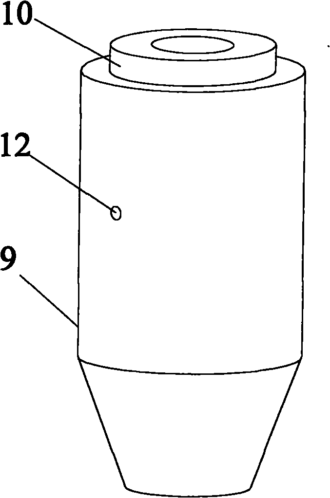
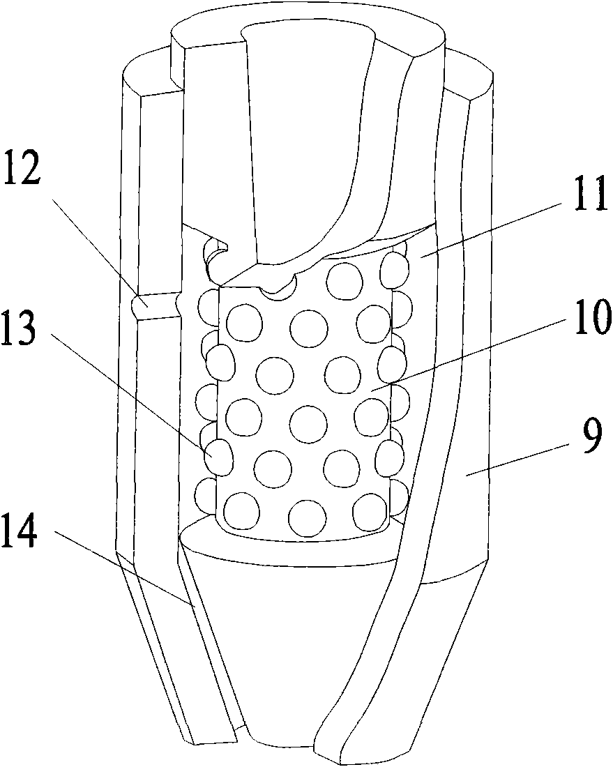
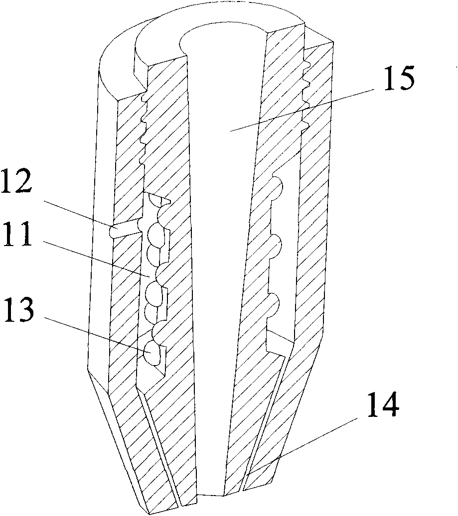
[0033] Figure 1 to Figure 5 shows the specific structure of this embodiment, such as figure 1 As shown, the laser nozzle device includes an outer casing 9 and a nozzle core 10 placed inside the outer casing 9, the side wall at the upper end of the outer casing 9 has a powder inlet 12, and the powder inlet 12 is externally connected to the powder inlet pipeline; figure 2 As shown, a powder outlet 14 is provided between the lower end of the jacket 9 and the lower end of the nozzle core 10; a powder channel 11 is provided between the inner side of the jacket 9 and the outer side of the nozzle core 10, and the powder channel 11 extends to the powder outlet 14 places, and the powder inlet 12, the powder channel 11, and the powder outlet 14 are connected to each other; as figure 2 As shown, the outer wall of the nozzle core 10 is inlaid with several steel balls 13, and the nozzle core 10 is provided with a laser channel 15, such as image 3 Shown; the upper end of the jacket 9 ...

Embodiment 2

[0047] This embodiment has the same structure as Embodiment 1 except the following features: the distance between the centers of the steel balls is 3 times the diameter of the steel balls, and the diameter of each steel ball is 2 mm.

[0048] There are 6 powder inlets, and each powder inlet is uniformly arranged around the central axis of the jacket.

[0049] The distance between the top end of the steel ball 13 facing the outer shell and the inner wall of the outer shell 9 is 5mm.

Embodiment 3

[0051] The structure of this embodiment is the same as that of Embodiment 1 except for the following features: the distance between the centers of the steel balls is twice the diameter of the steel balls, and the diameter of each steel ball is 1mm.

[0052] There are three powder inlets, and each powder inlet is uniformly arranged around the central axis of the jacket.

[0053] The distance between the top end of the steel ball 13 facing the outer shell and the inner wall of the outer shell 9 is 3mm.


PUM


Abstract

The invention discloses a laser nozzle device. The device comprises an outer sleeve and a nozzle core arranged in the outer sleeve, wherein the side wall at the upper end of the outer sleeve is provided with a powder inlet externally connected with a powder inlet pipe; a powder outlet is arranged between the lower end of the outer sleeve and the lower end of the nozzle core; a powder channel is arranged between the inner side of the outer sleeve and the outer side of the nozzle core and extended to the powder outlet, and the powder inlet, powder channel and powder outlet are intercommunicated; the outer side wall of the nozzle core is embedded with a plurality of steel balls, and a laser channel is arranged in the nozzle core; and the upper of the outer sleeve is muff-coupled with the upper end of the nozzle core. The invention also provides a method for uniformly distributing powder by the device. Because the device uses the steel balls, the uniform conveying of powder is realized without needing a longer power-conveying channel, so that the overall size of the nozzle is reduced, the complexity of a powder-conveying system matched with the device is greatly lowered, and the operability of the nozzle device is improved.

Description

technical field [0001] The invention belongs to the field of laser processing, in particular to a laser nozzle device and a method for evenly distributing powder thereof. Background technique [0002] Laser processing technologies such as laser cladding, laser remanufacturing, laser spraying, and laser lamination manufacturing have received more and more attention since they came out. They have the advantages of protecting the environment, reducing energy consumption, saving strategic metals, and improving the surface properties of materials. The advantages make it of great significance to study and improve it. Among them, laser cladding is one of the widely used technologies. Laser cladding is also called laser cladding or laser cladding. The method of melting the thin layers on the surface of the material together forms a metallurgically-bonded cladding layer on the surface of the base. [0003] In the application of laser processing technology, the laser nozzle is one o...

Claims


Application Information

Patent Timeline
IPC IPC(8): C23C24/10B23K26/34B23K26/14B23K26/342
Inventor 杨永强苏旭彬王迪
Owner SOUTH CHINA UNIV OF TECH
Why Eureka
Try Eureka