Uniaxial single spindle box of high-speed needling machine

A technology of spindle box and acupuncture machine, applied in acupuncture machine, transmission box, mechanical equipment and other directions, can solve the problems of unfavorable lubricating oil sealing, uneven force, excessive volume of the spindle box, etc., to meet the requirements of design and use requirements, easy installation and maintenance, improving the effect of unreasonable structures

Inactive Publication Date: 2011-01-12
JIANGSU YIZHENG HAIRUN TEXTILES MACHINERY
View PDF0 Cites 2 Cited by
  • Summary
  • Abstract
  • Description
  • Claims
  • Application Information

AI Technical Summary

Problems solved by technology

The main problems of the original spindle box are as follows: 1) The volume of the spindle box is too large, which is inconvenient for processing, transportation, assembly, etc.; 2) The fixed distance between the two push rods cannot reduce the number of push rods , also limited by the size of the spindle box, the number of the spindle box cannot be reduced, which leads to the inability to reduce the cost of the acupuncture machine; 3) There are too many parts participating in the rotation in the spindle box, which increases the temperature of the lubricating oil, which is not conducive to lubrication Oil seal; 4) The original structure of the main shaft housing is unreasonable, which is not conducive to the cooling of the lubricating oil; 5) The split combination of the main shaft and the cam has a small error in secondary processing; 6) The bearing supporting the connecting rod The fulcrum is 1 on average, and the force is relatively uneven

Method used


Image

  • Uniaxial single spindle box of high-speed needling machine
  • Uniaxial single spindle box of high-speed needling machine
  • Uniaxial single spindle box of high-speed needling machine

Examples


Embodiment Construction

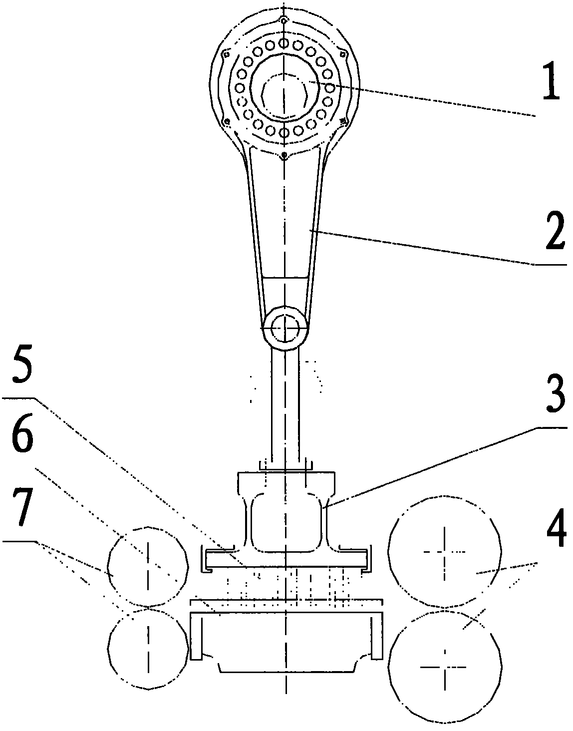
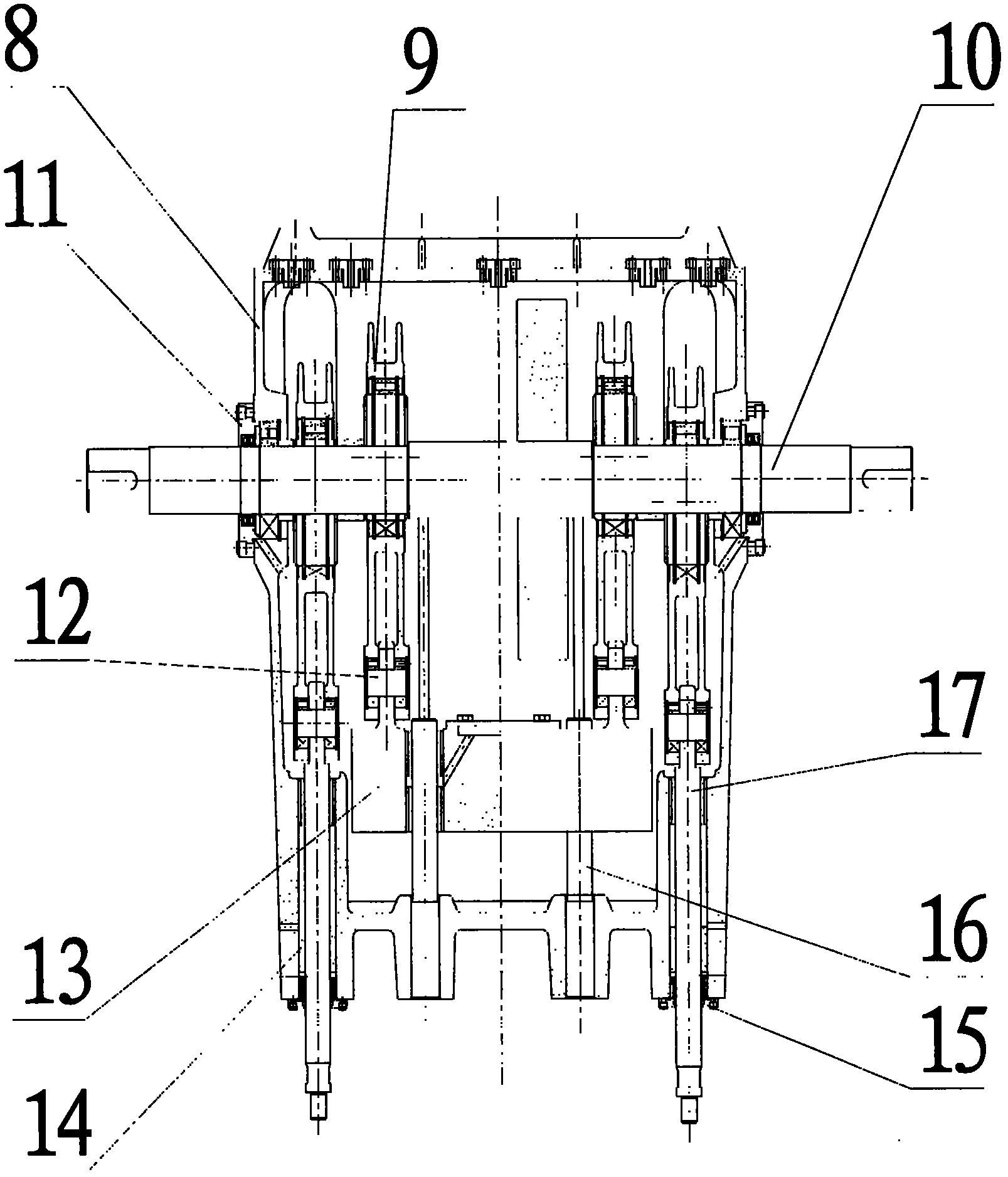
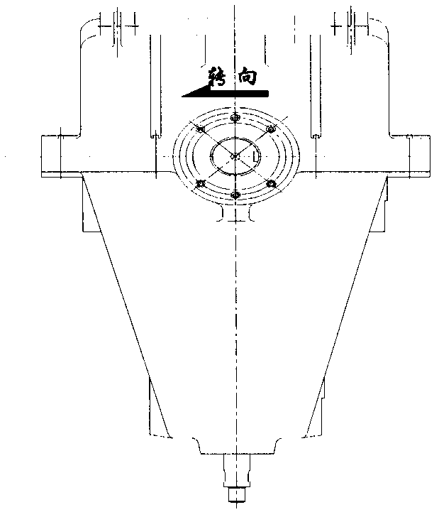
[0021] combine Figure 4 , Figure 5 , a single-axis single headstock of the present invention, including a headstock body 22, a headstock cover 18, a camshaft 21, a first connecting rod 23, a second connecting rod 32, a first connecting rod pin 24, a second connecting rod Rod pin 36, push rod 30, guide rod 39, first guide sleeve 26, second guide sleeve 40, small sliding sleeve 27, spindle end cover 20, lower end cover 28, lower boring cover 41, first roller bearing 19, Second roller bearing 33, third roller bearing 25, fourth roller bearing 37, balance weight 38, counterweight 35;

[0022] The headstock cover 18 is fixedly connected on the top of the headstock 22 by screws, the camshaft 21 is fixed on the headstock through the roller bearing and the head cover 20, and a spacer 34 is arranged between the roller bearing and the head cover 20, and the cam shaft The flywheel 31 is fixedly connected on the shaft 21, and the first roller bearing 19 is arranged in the hole of the ...


PUM


Abstract

The invention discloses a uniaxial single spindle box of a high-speed needling machine, comprising a spindle box body, a spindle box cover, cam shafts, connecting rods, connecting rod pins, a push rod, guide sleeves, a balance block, a guide rod, a balancing weight, and the like, wherein the spindle box body and the spindle box cover are fixedly connected to form a whole body through screws, the cam shafts are fixed on the spindle box through a two-disc roller bearing and a spindle end cover, the large head ends of the two connecting rods are sleeved on the two cam shafts after being located by a snap spring through the roller bearing, the small head ends of the two connecting rods are respectively connected with the push rod and the guide rod to form a whole body through a two-disc bearing, and location of up and down movement of the push rod and the guide rod is finished by the two guide sleeves fixed on the spindle box body. Compared with the prior art, the single spindle box has the advantages of small volume and convenient installation and maintenance, perfects the functions of the traditional spindle box and can determine the configuration amount of the spindle box according to the stress condition of needle punched fabrics so as to reach the purpose of cost control and ensure that the performance price ratio of the needling machine is more reasonable.

Description

technical field [0001] The invention relates to a spindle box of an acupuncture machine, in particular to a single-shaft single spindle box of a high-speed acupuncture machine. Background technique [0002] Needle punching nonwovens is the most common and extensive production method in the production process of nonwoven materials. Due to the characteristics of good permeability, excellent filtration performance and mechanical properties, needle-punched nonwovens are widely used in various industries such as geotechnical materials, filter materials, building waterproof materials, automotive interiors, synthetic leather substrates, and paper-making blankets. Non-woven fabric materials for daily use and daily use. At present, the output of needle-punched nonwovens accounts for about a quarter of the total nonwovens. Moreover, acupuncture nonwovens have many advantages such as simple processing technology, short process, flexible and convenient equipment combination, many type...

Claims


Application Information

Patent Timeline
Patent Type & Authority Applications(China)
IPC IPC(8): F16H37/12F16H53/02F16H57/00F16H57/02D04H18/00D04H18/02F16H57/021F16H57/023F16H57/027F16H57/04
CPCD04H18/02
Inventor 鞠永农徐祥周一江
Owner JIANGSU YIZHENG HAIRUN TEXTILES MACHINERY
Why Eureka
Try Eureka