
Reconfigurable long-period optical fiber grating coupler

A fiber grating, long-period technology, applied in the direction of cladding fiber, optical waveguide light guide, etc., can solve the problem of non-reconfigurable fiber coupler

Inactive Publication Date: 2011-01-12
UNIV OF ELECTRONICS SCI & TECH OF CHINA
View PDF0 Cites 8 Cited by
  • Summary
  • Abstract
  • Description
  • Claims
  • Application Information

AI Technical Summary

Problems solved by technology

Therefore, the fiber coupler made by the above method is not reconfigurable

Method used


Image

  • Reconfigurable long-period optical fiber grating coupler
  • Reconfigurable long-period optical fiber grating coupler
  • Reconfigurable long-period optical fiber grating coupler

Examples


Embodiment 1

[0029] figure 1 It is a structural diagram of a specific implementation of the long-period fiber grating coupler of the present invention, figure 2 Is its side view.

[0030] In this embodiment, the reconfigurable long-period fiber grating coupler is a dual-fiber long-period fiber grating coupler, which can be implemented according to the following steps:

[0031] 1. Put the two single-mode bare fibers coated with liquid matching medium into the protective sleeve 3, and put the protective sleeve 3 with two single-mode bare fibers inside into the bottom of the force applying unit 2 of the force applying device , In this embodiment, such as image 3 As shown, the force application unit 2 is a plug-in V-shaped groove, and its angle can be 1°~180°;

[0032] 2. The force applying unit 1 of the force applying device, in this embodiment, is as Figure 4 As shown, the force applying unit 1 is a plug-in V-shaped groove, the angle of which can be 1°~180°, and it is inserted into the force app...

Embodiment 2

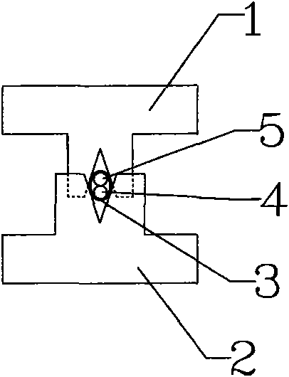
[0039] Such as Image 6 As shown, in this embodiment, the reconfigurable long-period fiber grating coupler is a dual-insertion right-angle ∏-shaped slot-paired dual-fiber coupler. In the figure, force applying units 1 and 2 are plug-in right-angle ∏-shaped grooves, 3 are protective sleeves, and 4 and 5 are single-mode bare fibers.

Embodiment 3

[0041] Such as Figure 7 As shown, in this embodiment, the reconfigurable long-period fiber grating coupler is a dual-insertion type U-slot paired dual-fiber coupler. In the figure, the force applying units 1 and 2 are plug-in U-shaped grooves, 3 is a protective sleeve, and 4 and 5 are single-mode bare fibers.

[0042] In Embodiments 1 to 3, any one of the single-mode bare fibers 4 and 5 can be used as a transmission fiber, and the other fiber is a coupling fiber, and they can form a 2×2 fiber coupler.


PUM

PropertyMeasurementUnit
Angleaaaaaaaaaa
Angleaaaaaaaaaa
Thicknessaaaaaaaaaa

Abstract

The invention discloses a reconfigurable long-period optical fiber grating coupler, comprising a force applying device and a plurality of tightly-arranged single-mode naked optical fibers arranged in a protective sleeve; and the force applying device periodically applies the radial pressure in the axial transmission direction of the single-mode naked optical fibers, thus gratings with the same space change period are written on the axial transmission direction of the single-mode naked optical fibers due to the microbend effect and the photoelastic effect. When the space period of the optical fiber grating leads a fiber core base mode and a high-order cladding mode to satisfy the phase matching condition, the fiber core base mode and the cladding modes between the optical fibers are coupled with each other; the cladding mode between the optical fibers are coupled with each other through the action of a vanishing field; the coupler function is realized on the plurality of naked optical fibers based on the coupling and period radial pressure; as being generated only by the external force, the long-period optical fiber grating is an optical fiber grating coupler which is easy to write and erase, can be used in the optical network to serve as a devices such as flexible add-drop multiplexers and optical power distributors and the like.

Description

Technical field [0001] The present invention relates to the technical field of information optics and optoelectronic devices, in particular to a reconfigurable long-period fiber grating coupler in optical communication technology. Background technique [0002] Optical fiber coupler is the most commonly used optical passive device in optical fiber communication and optical fiber sensing technology. It can be used as optical beam combiner, splitter, wavelength division multiplexer, etc. There are several manufacturing methods for fiber couplers: [0003] 1. Production of single-mode fiber coupler by melt stretching method [0004] The two single-mode bare optical fibers are melted and stretched by electric discharge heating, so that the outer diameter of the optical fiber is reduced, and the cladding of the optical fiber is melted together in the coupling area to make the core of the fiber close together. The coupling between the fibers is enhanced by the evanescent field, which incr...

Claims


Application Information

Patent Timeline
IPC IPC(8): G02B6/02
Inventor 周晓军陈成金刘东彭水海张旨遥黎晓云
Owner UNIV OF ELECTRONICS SCI & TECH OF CHINA
Learn More