Antenna selection method and device for mobile terminal
A mobile terminal antenna and mobile terminal technology, applied in the field of mobile communication, to achieve the effects of enhancing transmission performance, avoiding long-term fading, and reducing costs
- Summary
- Abstract
- Description
- Claims
- Application Information
AI Technical Summary
Problems solved by technology
Method used
Image
Examples
Embodiment 1
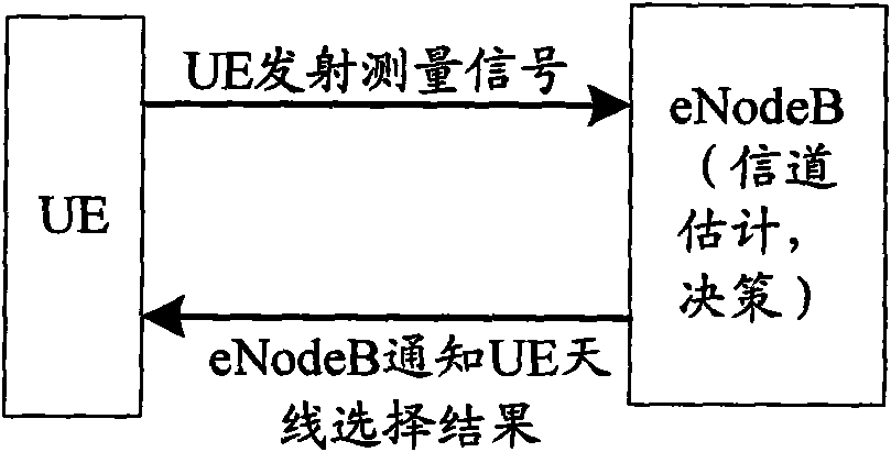
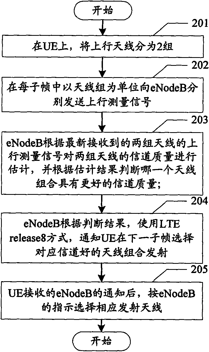
[0054] In this embodiment, the UE is in FDD mode. In this embodiment, the antenna selection signaling of LTE release8 is reused to instruct the terminal to select an antenna group with good channel quality for combined transmission, as shown in figure 2 As shown, the specific steps are as follows:
[0055] Step 201, grouping UE uplink transmit antennas;
[0056] Grouping antennas may be based on a certain set principle, for example, based on antenna correlation, based on capacity, and so on. In this embodiment, the principle of antenna correlation is adopted to group the uplink antennas of the UE, and two antennas with less correlation are selected as a group, and there are two groups in total. The grouping in this embodiment is a fixed grouping, and in each subframe , the two antennas of a group always transmit and receive signals as a whole.
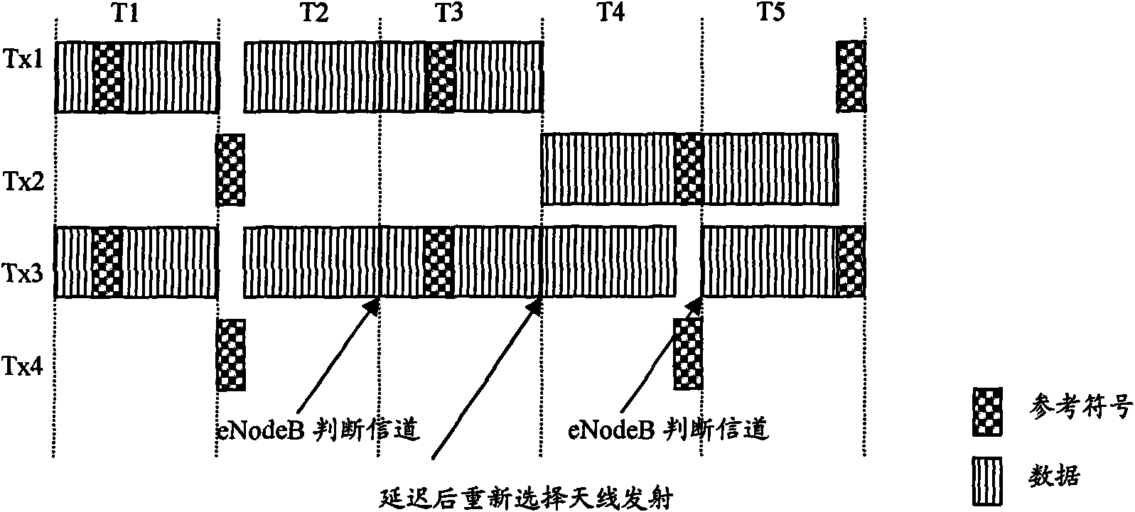
[0057] Step 202, based on the antenna grouping, send the uplink reference measurement signal to the eNodeB in units of antenna gro...
Embodiment 2
[0065] In this embodiment, in the FDD mode, antenna selection is realized by adding new downlink control information (Downlink Control Information, DCI), that is, adding antenna selection indication information in 6 states, such as Figure 4 As shown, the specific process is as follows:
[0066] Step 401, group the uplink transmit antennas of the UE;
[0067] In this embodiment, a non-fixed grouping method is adopted, and which two antennas are specifically selected for transmission is indicated through newly added antenna selection indication information of 6 states.
[0068] Step 402, sending the uplink reference measurement signal on the four antennas of the two antenna groups in each subframe;
[0069] Step 403: In each subframe, the eNodeB estimates the uplink channel quality according to the received uplink reference measurement signal; sorts the four antennas according to the estimation result;
[0070] Step 404, the eNodeB comprehensively judges which two antennas ha...
Embodiment 3
[0077] In the TDD mode UE's autonomous antenna selection process based on reciprocity, such as Figure 7 Shown:
[0078] Step 701, the eNodeB sends a downlink reference measurement signal to the UE, and the UE receives the downlink reference measurement signal;
[0079] Step 702, the UE estimates the quality of the downlink channel by using the channel reciprocity characteristic of the TDD system, and then infers the quality of the uplink channel;
[0080] Step 703, the UE autonomously decides to select an antenna group with better uplink channel quality for transmission.
[0081] For the TDD system, if the UE cannot utilize channel reciprocity in certain scenarios (such as a Doppler frequency shift environment), the uplink channel measurement can be implemented in a manner similar to FDD. One option is to treat the four uplink antennas as two antenna groups. For this antenna selection method, the antenna signaling notification method of LTE release8 can be reused, so that t...
PUM
 Abstract
Description
Claims
Application Information
 - R&D
- Intellectual Property
- Life Sciences
- Materials
- Tech Scout
- Unparalleled Data Quality
- Higher Quality Content
- 60% Fewer Hallucinations
Browse by: Latest US Patents, China's latest patents, Technical Efficacy Thesaurus, Application Domain, Technology Topic, Popular Technical Reports.
© 2025 PatSnap. All rights reserved.Legal|Privacy policy|Modern Slavery Act Transparency Statement|Sitemap|About US| Contact US: help@patsnap.com


