Double-direction automatic profiling turning machine

A profiling turning and automatic technology, which is applied in the direction of woodworking lathes, wood processing equipment, manufacturing tools, etc., can solve the problems that the accuracy and size of the workpiece cannot be guaranteed, the labor intensity of the operator is high, and the non-processing time of the machine tool is long. The effect of strengthening rigidity, reducing labor intensity and improving precision

Inactive Publication Date: 2011-01-19
王斌 +2
View PDF6 Cites 4 Cited by
  • Summary
  • Abstract
  • Description
  • Claims
  • Application Information

AI Technical Summary

Problems solved by technology

[0002] Most of the existing equipment for processing bamboo and wood rod-shaped workpieces use ordinary lathes or general profiling machine tools, almost all of which are operated by hand. Tightly locate one end of the workpiece; during processing, the tool is generally moved from the tail end of the machine tool to the spindle box in one direction, and the contour size of each part of the workpiece is realized by manually shaking and controlling the advancement and retreat of the middle carriage, and then controlling the cutting depth of the tool; when lowering the workpiece, it is necessary Then turn the handwheel to loosen and retreat the top, and move the tool position from one end of the spindle box to the end of the machine tool in the empty space, and repeat the operation after changing the workpiece, repeating the cycle
Due to the laborious and complicated operation, the labor intensity of the operators of this type of equipment is high, and the non-processing of the machine tool takes a lot of time, resulting in low production and processing efficiency.
More importantly, since this type of equipment is all manually operated by the operators, due to the differences in the technical level or action response of the operators, the accuracy and dimensional consistency of the workpieces obtained by batch processing cannot be guaranteed, and the rate of defective products is also low. higher

Method used


Image

  • Double-direction automatic profiling turning machine
  • Double-direction automatic profiling turning machine
  • Double-direction automatic profiling turning machine

Examples


Embodiment Construction

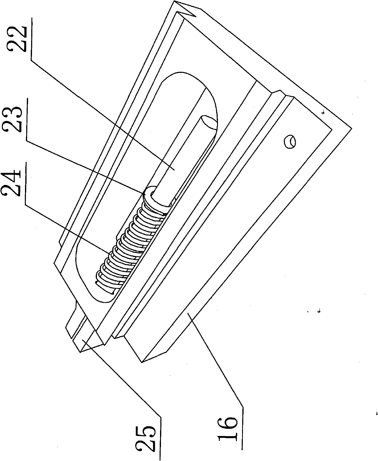
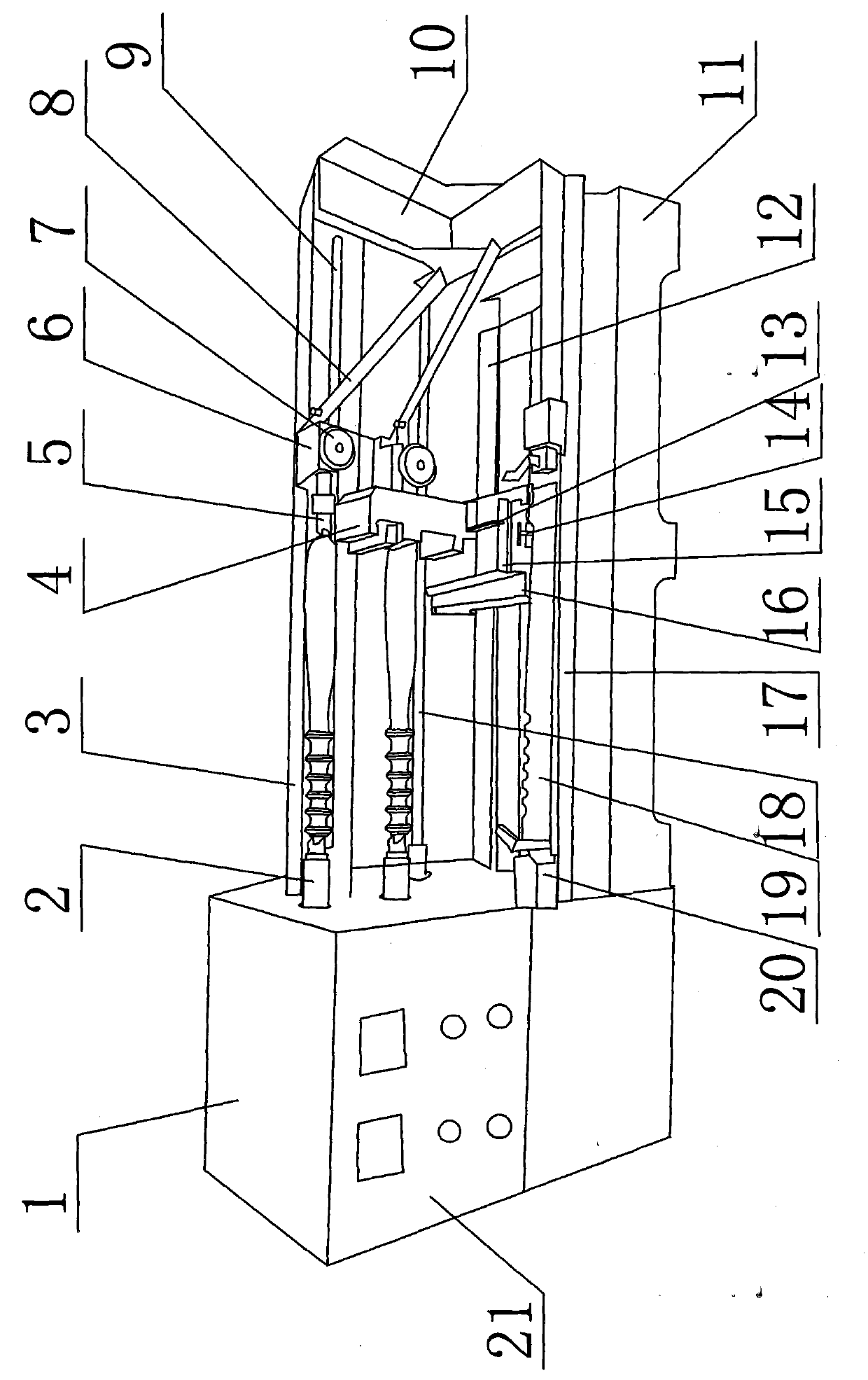
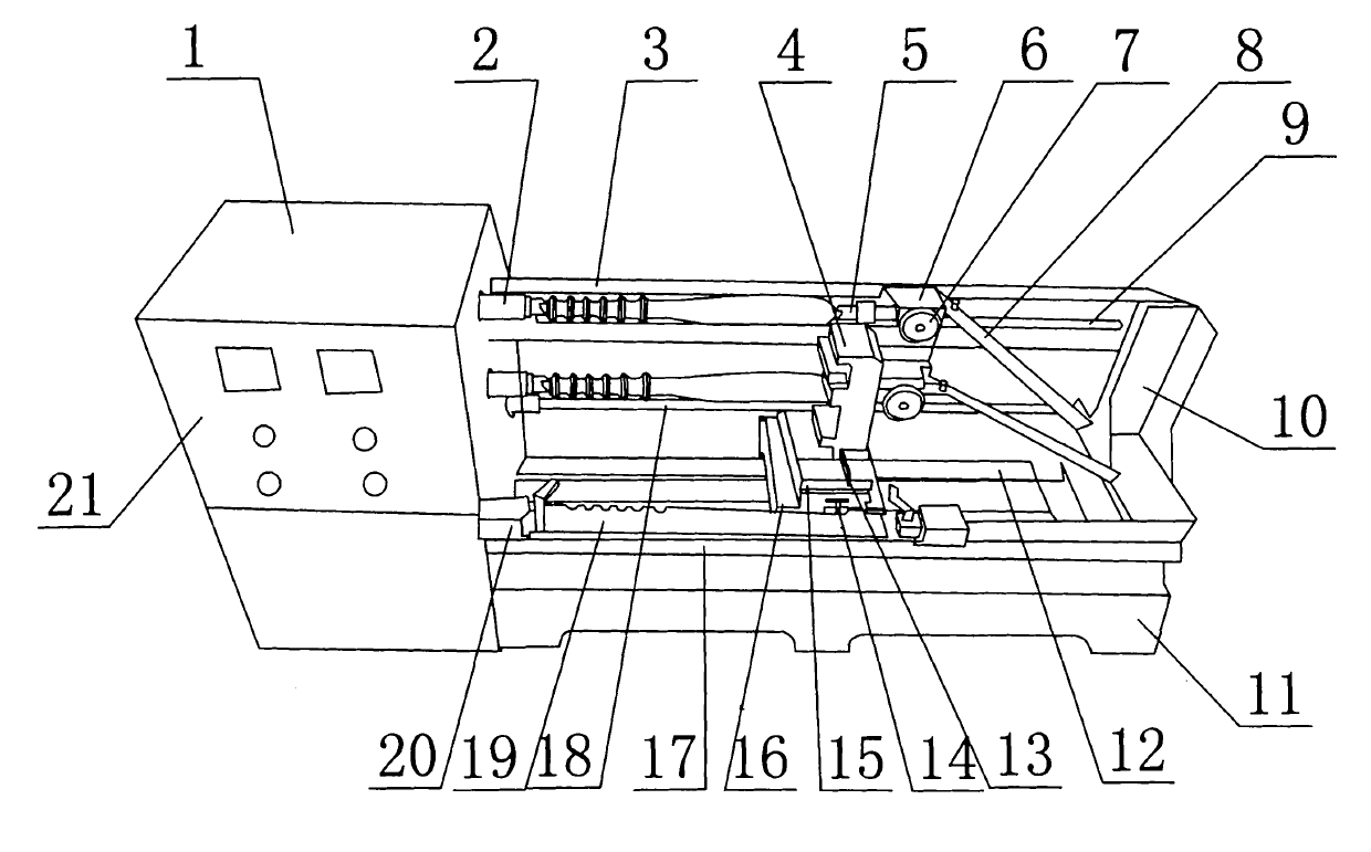
[0030] Such as figure 1 , 2 As shown, the two-way automatic profiling turning machine of the present invention includes a bed 11, a transverse guide 12 is provided on the bed 11, a headstock 1 and a tail support 10 are installed on both ends of the bed 11, and the headstock 1 is provided There are a control panel 21 and two main shafts 2. The control panel 21 is equipped with various switches. A transmission screw 18 is installed between the main shaft box 1 and the tail support 10. The large carriage 16 is connected to the transmission through the screw nut base 25 The screw rod 18 is connected, the chute on the bottom surface of the large carriage 16 is matched with the horizontal guide rail 12, a small carriage 15 is installed on the large carriage 16, and the small carriage 15 is fixedly connected with a knife holder 4 and a knife holder 4. There are two tool installation positions.

[0031] A cross beam 3 and a profiled beam 17 are also installed between the spindle box 1 an...


PUM


Abstract

The invention discloses a double-direction automatic profiling turning machinecomprising a lathe bed which is provided with a lateral guide rail, a spindle box and a tail support, wherein a driving lead screw is arranged between the spindle box and the tail support; a big planker is connected to the driving lead screw and is provided with a small planker; the small planker is fixedly connected with a tool apron; a crossbeam and a profiling beam are respectively arranged between the spindle box and the tail support; the crossbeam is provided with a lateral guideway; a tail stock is installed in the lateral guideway; the plane on which the axial extension cord of the movable tip of the tail stock is arranged is provided with a draw bar; the profiling beam is provided with a master plate; one side of the small planker, which approaches to the profiling beam, is provided with a profiling needle roller; during operation, the profiling needle roller is abutted against the working surface of the master plate; and a spring pushing mechanism is arranged between the big planker and the small planker. The turning machine of the invention lowers labor intensity and improves working efficiency and the precision of the product.

Description

Technical field [0001] The invention relates to a turning machine, in particular to a two-way automatic profiling turning machine. Background technique [0002] Existing equipment for processing bamboo and wood rod-shaped workpieces, most of them use ordinary lathes or general profiling machine tools, and they are almost all manually operated. The production process is roughly as follows: when the workpiece is loaded, the hand wheel needs to be manually shaken to top the tailstock. Tightly position one end of the workpiece; during machining, the tool is generally moved in one direction from the end of the machine tool toward the headstock. The contour dimensions of each part of the workpiece are controlled by manually shaking the middle carriage to control the depth of the cutting tool; Then manually turn the hand wheel to make the center loose and retreat, and move the tool position from one end of the headstock to the end of the machine tool. Repeat the operation after changing...

Claims


Application Information

Patent Timeline
IPC IPC(8): B27C7/00
Inventor 王斌
Owner 王斌
Why Eureka
Try Eureka