Tube-pin bending machine for helical tubes

A screw-type, bending machine technology, applied in glass forming, glass re-forming, glass manufacturing equipment and other directions, can solve the problem that the shape of lamp pins cannot be standardized, the labor intensity of operators is high, and the quality of products is affected. and other problems, to achieve the effects of good product quality, long service life and lower production costs

Inactive Publication Date: 2011-01-19
杭州临安禾强电器有限公司
View PDF3 Cites 6 Cited by
  • Summary
  • Abstract
  • Description
  • Claims
  • Application Information

AI Technical Summary

Problems solved by technology

The defects of manual bending pins are obvious: not only the shape of the lamp pins cannot be standardized, which affects the quality of the product, but also the production efficiency is too low, the production environment is poor for high temperature operations, and the labor intensity of the operators is high.

Method used


Image

  • Tube-pin bending machine for helical tubes
  • Tube-pin bending machine for helical tubes
  • Tube-pin bending machine for helical tubes

Examples


Embodiment Construction

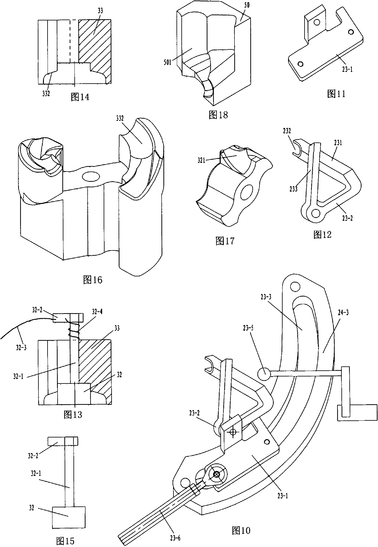
[0045] As shown in the figure, in the spiral lamp tube bending machine, a strip-shaped frame 20 is arranged, and the conveyor belt driven by the gap mechanism is positioned end-to-end between the head and the tail of the machine. The positioning molds for processing the lamp tubes are evenly arranged in a line on the conveyor belt 6, and the loading and unloading lamp tube station 2, oven 3, heating torch 21 and foot bending station 5 are also arranged in sequence from the head to the tail of the machine;

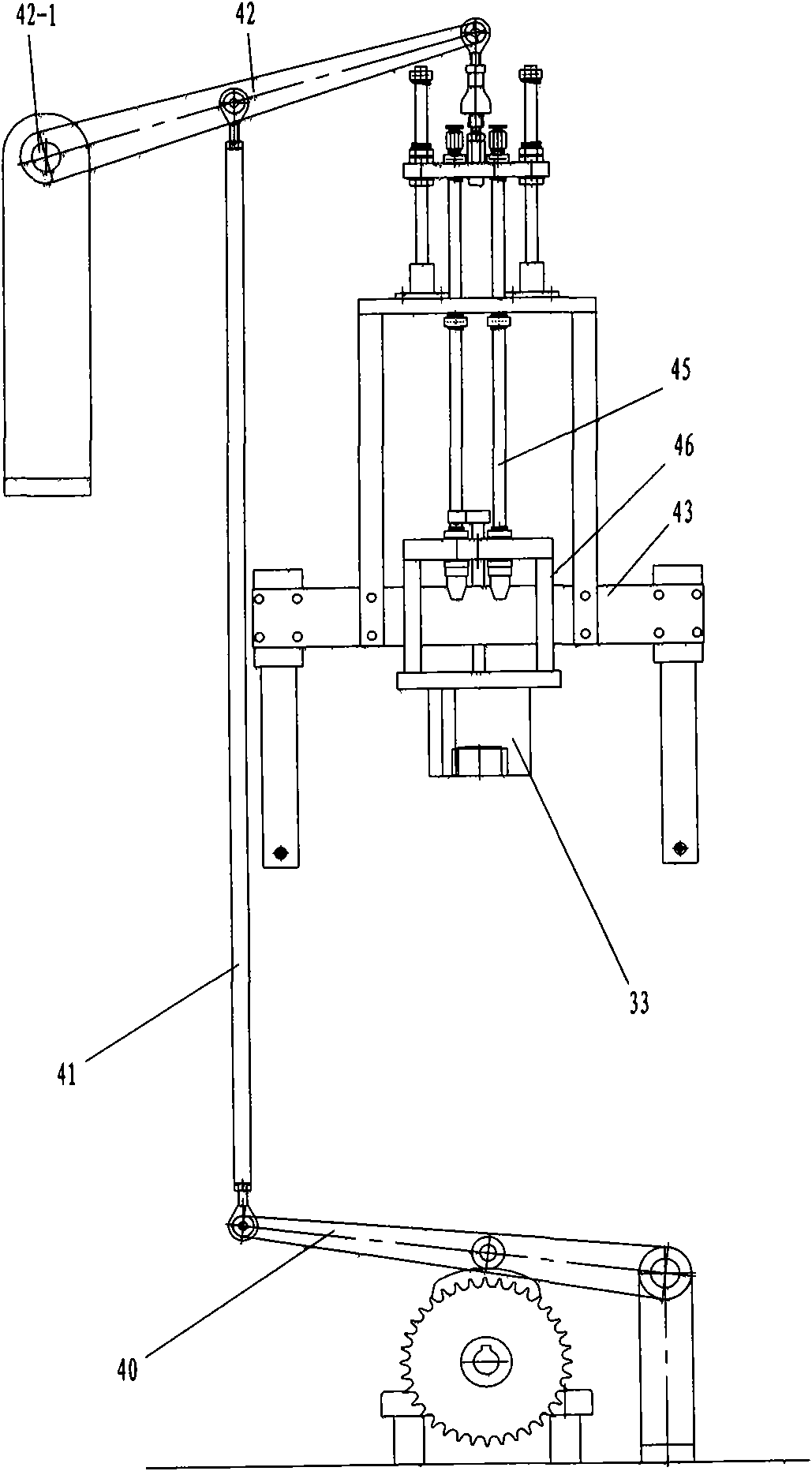
[0046]The foot-bending station is provided with a bending-foot mechanism driven by a driving mechanism to bend the softened pin according to the set requirements; the driving mechanism adopts a conventional crank-link mechanism.

[0047] The conveyor belt is a chain arranged at the center of the frame, and the chain is wrapped around four chain wheels 6-1 from the head to the tail and connected end to end to form a circle; the driving wheel in the chain wheel is driven by a ...


PUM


Abstract

The invention relates to electric light source equipment, in particular to a device for bending a tube pin of a helical energy-saving lamp tube. The invention aims to provide a tube-pin auto-bending machine for helical tubes, and the machine can bend the tube pin automatically and has the characteristics of good bending quality, high production efficiency and unified product standard. The technical scheme of the invention is as follows: the tube-pin bending machine for the helical tubes comprises an elongated frame, a conveyer belt which is positioned between a machine head and a machine tail end to end and driven by a clearance mechanism, and a plurality of positioning moulds which are uniformly arranged on the conveyer belt in a line and used for positioning processed tubes. Meanwhile, the tube-pin bending machine for the helical tubes also comprises a tube mounting/dismounting station, a drying oven, a heating rotor and a pin bending station which are sequentially arranged from the machine head to the machine tail, wherein the pin bending station is provided with a pin bending mechanism which is driven by a driving mechanism and used for bending the tube pin burned to be soft according to preset requirements; and the conveyer belt is a chain arranged in the center of the frame, and the chain respectively surrounds two chain wheels with horizontally-arranged axis from the machine head to the machine tail, and then form a circle end to end.

Description

technical field [0001] The invention relates to an electric light source device, in particular to a device for bending the pins of a spiral energy-saving lamp tube. Background technique [0002] Under the background of energy conservation and environmental protection in today's world, spiral energy-saving lamps have many advantages such as high luminous efficiency and energy saving, and their application range has also been expanded unprecedentedly. However, the lamp tube of the spiral energy-saving lamp has not yet been fully mechanized, which makes it difficult to further improve the production efficiency of the product and further reduce the production cost. [0003] The manufacturing process of the existing spiral energy-saving lamp tubes (also known as bright tubes; the fluorescent powder can only be coated after being bent into shape) is: first, the high-temperature softened glass straight tubes are bent into Spiral semi-finished lamp tube D1 (such as figure 1 shown)...

Claims


Application Information

Patent Timeline
Patent Type & Authority Applications(China)
IPC IPC(8): C03B23/045
CPCY02P40/57
Inventor 雷文元蒋纯校
Owner 杭州临安禾强电器有限公司
Why Eureka
Try Eureka