Pipe belt type wind turbine air cooler

A wind turbine, tube-belt technology, applied to wind turbine components, wind engines, wind power generation, etc., can solve the problems of shortening the service life of the motor, the decline of the heat dissipation performance of the air cooler, and the damage of the wind turbine, and achieves enhanced replacement. Heat, the effect of increasing air turbulence on the hot side

Active Publication Date: 2011-01-19
山东银轮热交换系统有限公司
View PDF5 Cites 3 Cited by
  • Summary
  • Abstract
  • Description
  • Claims
  • Application Information

AI Technical Summary

Problems solved by technology

However, due to the limited space in the height direction of the generator cabin, the tube bundle occupies a very high height space, which has caused great difficulties in the selection of fans, resulting in that the drainage circulation fan can only choose the structural form with a built-in small-sized motor
The motor of the drainage circulation fan built in the casing will generate a certain amount of heat due to operation, which will increase the heat dissipation load of the air cooler and weaken the cooling effect. Most importantly, the built-in motor will work in a high temperature environment for a long time, which will greatly shorten The service life of the motor, the increased failure rate, once the drainage circulation fan is damaged, the heat dissipation performance of the air cooler will drop sharply, which will cause the wind turbine to be damaged or shut down due to excessive temperature

Method used


Image

  • Pipe belt type wind turbine air cooler
  • Pipe belt type wind turbine air cooler
  • Pipe belt type wind turbine air cooler

Examples


Embodiment Construction

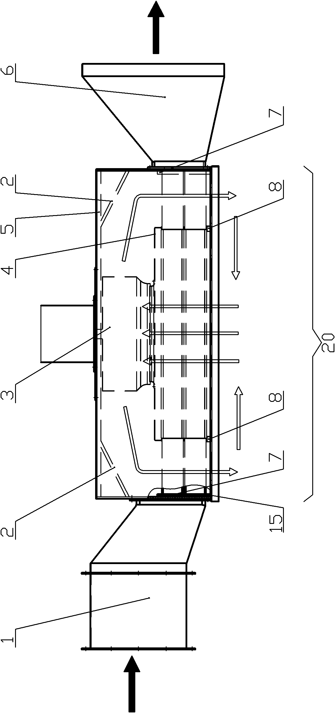
[0023] Below in conjunction with accompanying drawing, the present invention will be further described with specific embodiment, see Figure 1-7 :

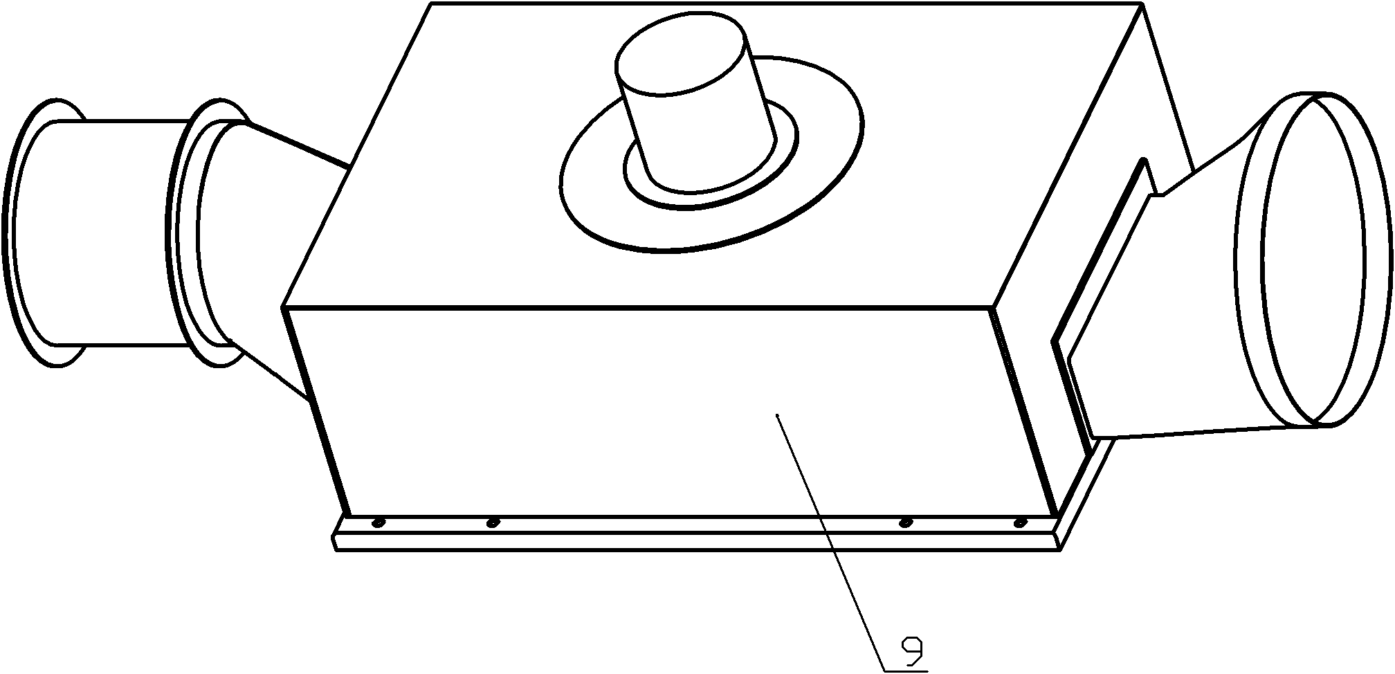
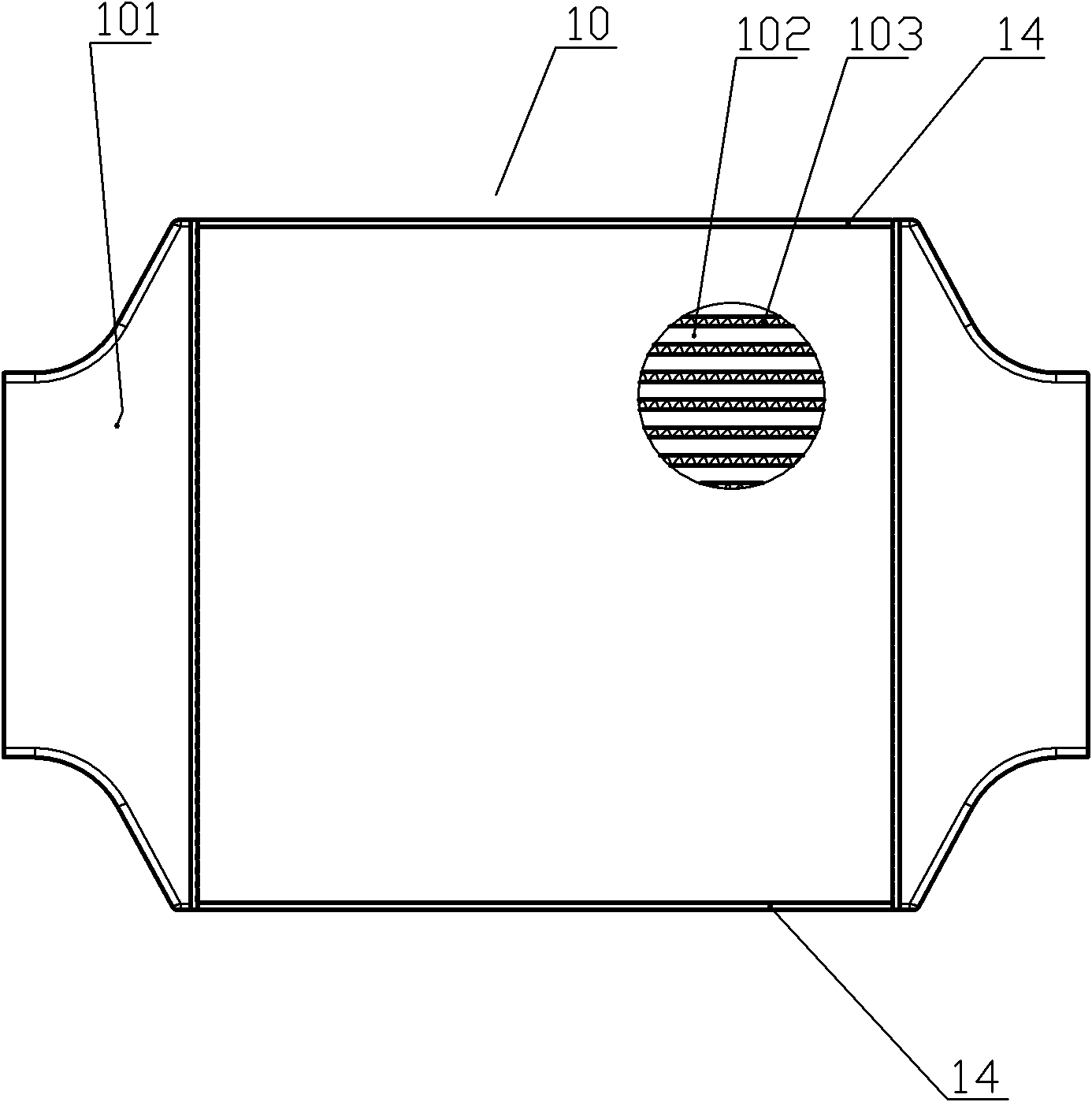
[0024] The tube-belt air-to-air cooler for wind turbines is fixed with a cold-side drainage fan 1 at one end of the cooler 20, with an air outlet 6 fixed at the other end, with a hot-air inlet in the middle, and hot-air outlets on both sides of the hot-air inlet. At the air outlet, several heat dissipation cores 10 are fixed in the cooler shell 9, and a hot side circulation fan 3 is fixed in the center of the uppermost side of the heat dissipation core 10. Several flat tubes 102 are arranged in the heat dissipation core 10 to form a flat tube bundle. A heat dissipation belt 103 is arranged between the flat tubes 102, a main board 104 is fixed at both ends of the flat tube bundle, and an air chamber 101 is fixed on the main board 104. Unicom, the other end communicates with the air exhaust port 6, the heat dissipation strips 103 o...


PUM


Abstract

The invention belongs to the technical field of coolers and relates to a pipe belt type wind turbine air cooler. One end of the cooler is fixed with a cold side induced draft fan, while the other side is fixed with an exhaust hole; the middle of the cooler has a hot air inlet and a hot air outlet; a plurality of radiation cores are fixed in the shell of the cooler; a hot side circulating fan is fixed in the middle of the upmost side of the radiation cores; the motor part of the hot side circulating fan is arranged outside the shell of the cooler; a plurality of flat pipes are arranged in the radiation cores; radiation belts are arranged between the flat pipes; the two ends of the radiation cores are fixed with a main board, and an air chamber is fixed on the main board; one end of each of flat pipe cavities in the radiation cores is communicated with the air outlet of the cold side induced draft fan, while the other side is communicated with the exhaust hole; the radiation belts of the radiation cores are communicated with the hot air inlet of the shell of the cooler; and the air chambers of all radiation cores are communicated with the space in the shell of the cooler and the hot air outlet of the shell of the cooler. The pipe belt type wind turbine air cooler has the advantages of high radiation efficiency, compact structure and contribution to motor radiation and service life prolongation.

Description

technical field [0001] The invention belongs to the technical field of pipe-belt type air coolers for wind power generators, and in particular relates to a pipe-belt structure air cooler applied to wind power generators to dissipate heat generated during the operation of the wind power generators. Background technique [0002] Wind turbines will continue to generate a large amount of heat during operation, which must be dissipated in time to ensure the normal operation of the generator set within a tolerable temperature range. [0003] The commonly used air coolers for wind turbines now have a bare tube bundle structure, which generally relies on the centrifugal force generated by the rotation of the rotor to drive the flow of air. The structure of this heat exchanger is relatively simple, but the wind pressure generated is small, the air flow is not smooth, and the cooling effect is poor. In order to improve this situation, a drainage circulation fan is usually installed o...

Claims


Application Information

Patent Timeline
Patent Type & Authority Applications(China)
IPC IPC(8): F03D11/00F28F1/12F03D80/60
CPCY02E10/722Y02E10/72
Inventor 范正银官百俊章帅胡永明
Owner 山东银轮热交换系统有限公司
Why Eureka
Try Eureka