Double-contact coaxial connector with switch

A technology of coaxial connectors and switches, which is applied in the direction of connection, two-part connection devices, parts of connection devices, etc., can solve the problem of increasing the signal coupling of the connection path and the disconnection path, uneven center of gravity, plugging and unplugging Problems such as large pulling angles can be achieved to improve radio frequency transmission indicators, reduce energy loss, and increase service life

Active Publication Date: 2011-01-19
ELECTRIC CONNECTOR TECH
View PDF5 Cites 4 Cited by
  • Summary
  • Abstract
  • Description
  • Claims
  • Application Information

AI Technical Summary

Problems solved by technology

[0006] The existing coaxial connector with switch mainly has two kinds of structures. One structure is: on the basis of the above-mentioned common coaxial connector with switch, the opening and closing direction of the switch switching mechanism is set to be the same as that of the plug pin. The plugging and unplugging directions are parallel. This structure occupies a large space on the printed circuit board, and it is difficult to achieve miniaturization and low height. Even if the structure can be miniaturized, it is very difficult to manufacture, and the reliability of assembly cannot be guaranteed. Consistency with quality; Another structure is: the opening and closing direction of the switch switching mechanism is set to be perpendicular to the insertion and extraction direction of the insertion pin, so that on the one hand, the structure reduces the occupation of the printed circuit board. The area is beneficial to save space, and on the other hand, it also reduces the difficulty of assembly and facilitates mass production. However, the existing coaxial connector with switch with this structure also has the following problems:
[0007] 1) Dust easily enters the contact part of the switch switching mechanism from the opening, resulting in poor switch operation;
[0008] 2) The transmission power loss of the incoming signal is relatively large, which is not conducive to the transmission and reception of the signal by the transceiver circuit inside the small electronic device;
[0009] 3) The assembly accuracy of the switch switching mechanism is not high, and the assembly is not firm. After assembly, due to the warping of the end of the static terminal, it is easy to leave the predetermined position, resulting in unstable contact performance between the static terminal, the moving terminal and the plug-in pin. Facilitate the application in the environment of vibration and shock;
[0010] 4) When the contact point of the contact part of the switch switching mechanism electrically connected to each other fails due to improper operation, environmental pollution or other reasons, the second contact point cannot be provided to continue to ensure the electrical connection of the contact;
[0011] 5) In actual use, the insertion angle of the plug-in pin may be too large, that is, the plug-in pin often forms a certain angle with the axial direction of normal plug-in, causing the plug-in pin to be inserted obliquely in the switch switching mechanism. Between the static terminal and the moving terminal, the distance between the connected signal path and the disconnected signal path is shortened, which increases the coupling of the signal on the path and the signal off the path, thereby reducing the radio frequency of the switching mechanism. Isolation performance;
[0012] 6) In order to meet the needs of miniaturized production process, the surface mount (SMT) method is often used to weld the coaxial connector with switch on the printed circuit board. Due to the uneven center of gravity (because some structures are too long in the direction of length etc.) or the flatness problem makes the positioning prone to deviation, or it is easy to be lifted by the molten tin, resulting in the position deviation of the product soldered to the printed circuit board, and the positioning accuracy is not high

Method used


Image

  • Double-contact coaxial connector with switch
  • Double-contact coaxial connector with switch
  • Double-contact coaxial connector with switch

Examples


Embodiment Construction

[0042] The coaxial connector with switch with double contacts of the present invention will be further described below in conjunction with the accompanying drawings.

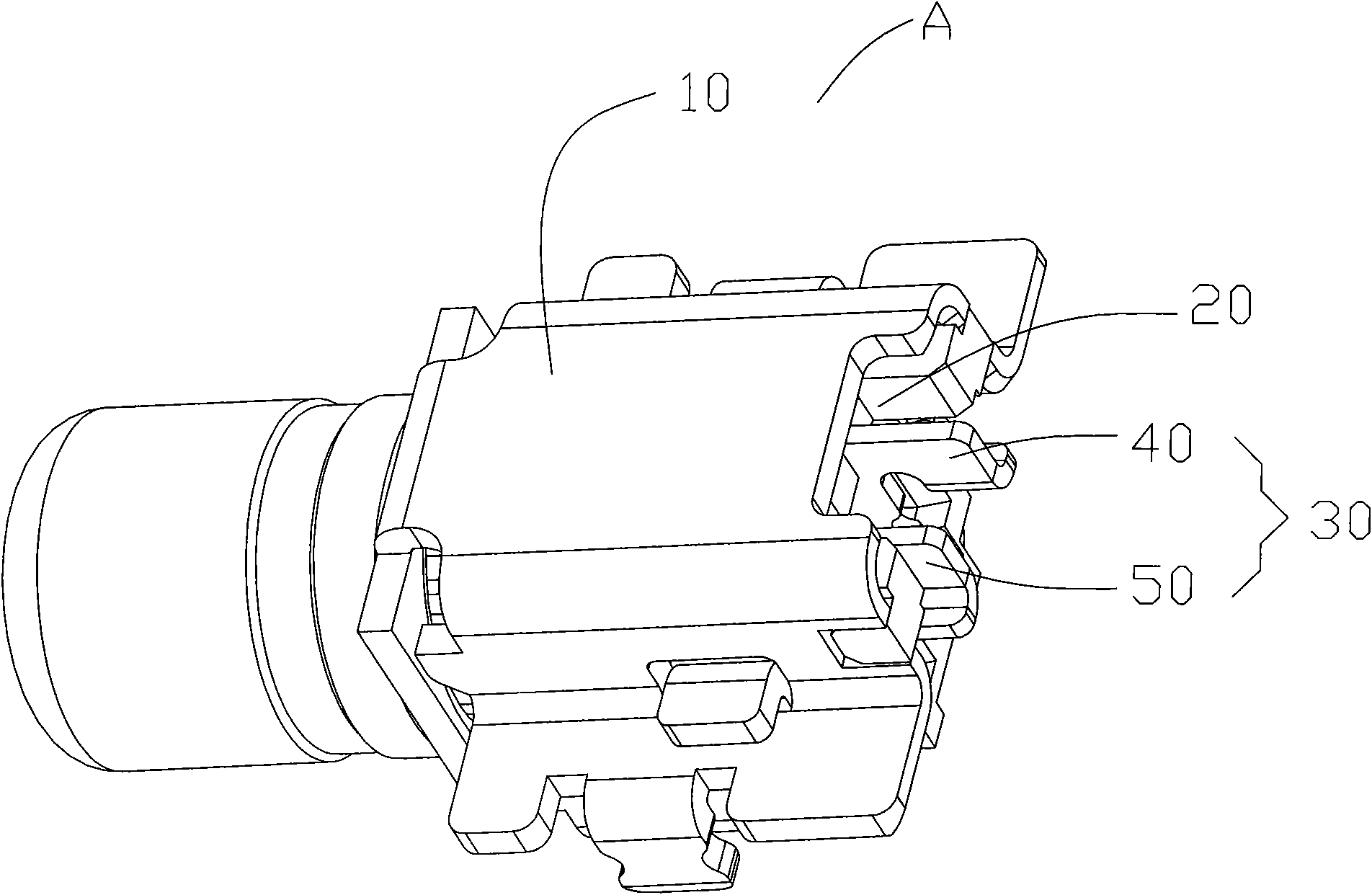
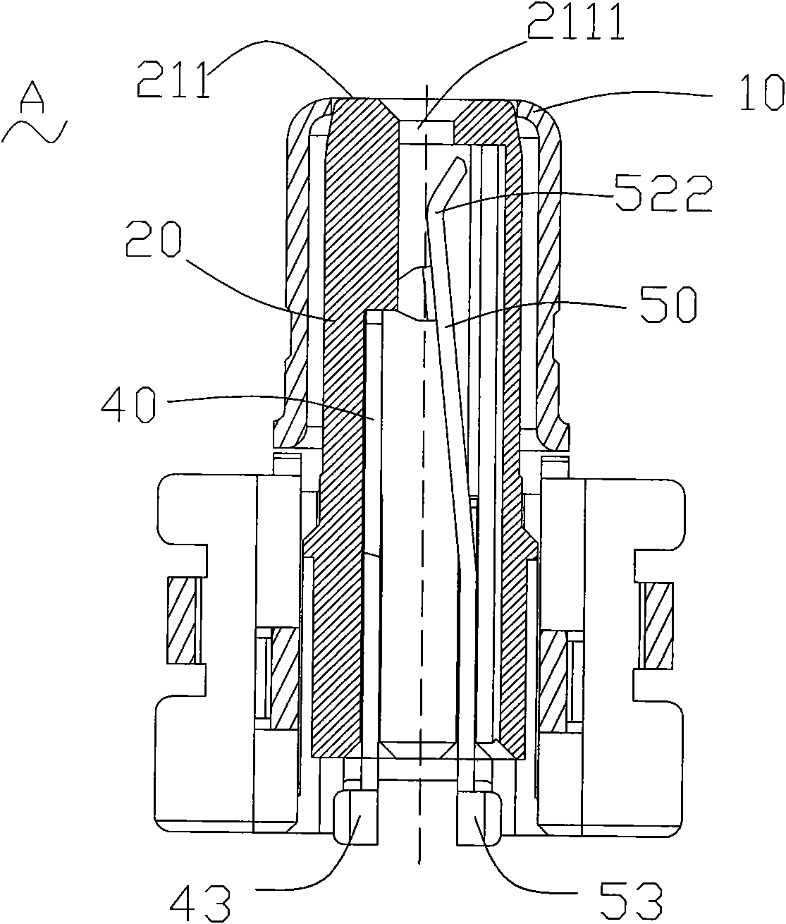
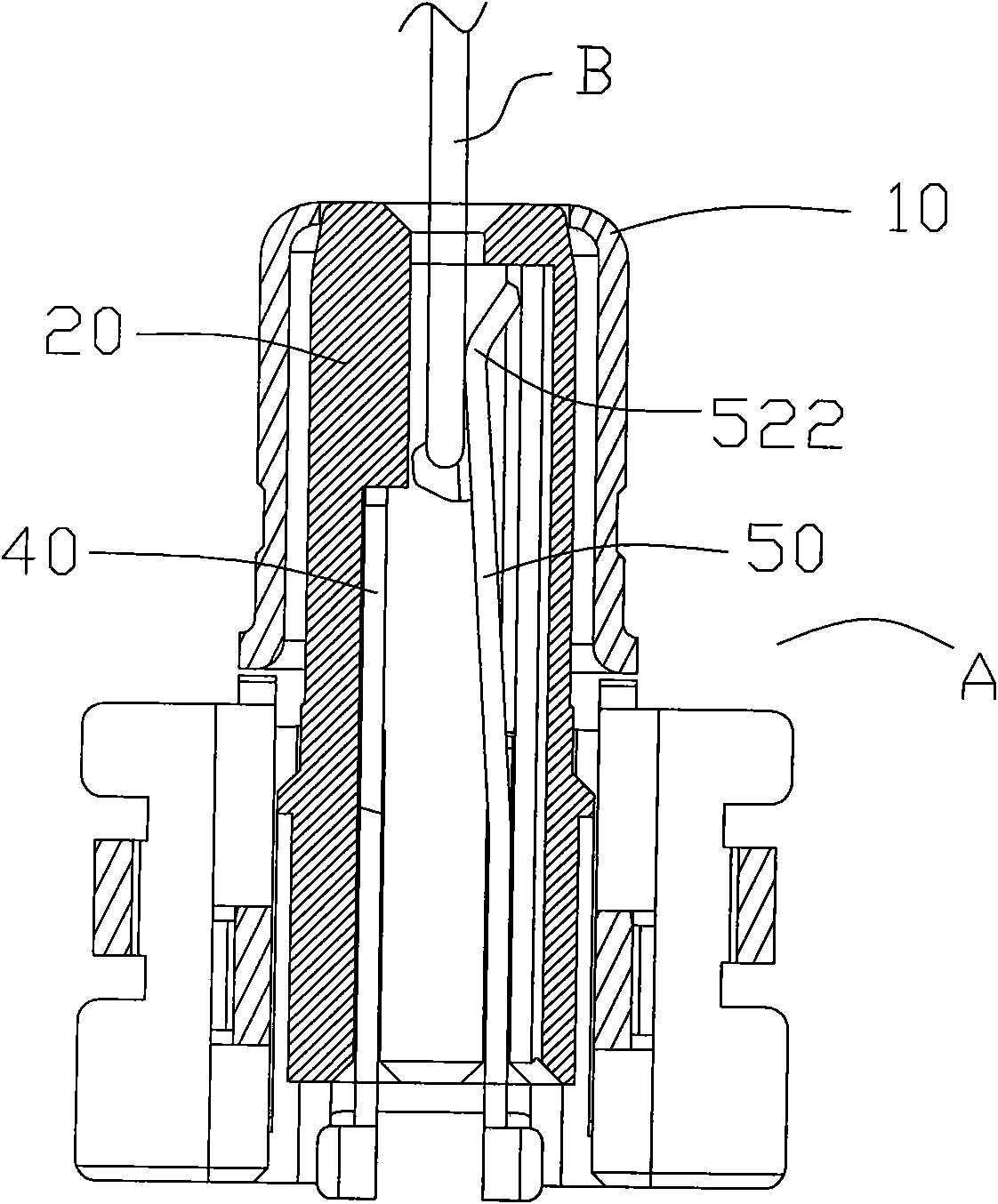
[0043] Such as figure 1 and 2a As shown, the coaxial connector A with switch with double contacts in the present invention includes an insulating fixing seat 20, a conductive shell 10 and a switch switching mechanism 30, wherein the conductive shell 10 is covered on the insulating fixing seat 20 On the outside, the switching mechanism 30 is disposed in the hollow cavity of the insulating fixing base 20; the switching mechanism 30 includes a movable terminal 50 and a fixed terminal 40 electrically connected to each other in use. When testing, such as Figure 2b The switching device 30 shown in the Figure 2b The conversion of the signal transmission circuit is completed by the plugging and unplugging of the plug-in pin B, that is, the electrical connection between the movable terminal 50 and the fixed terminal...


PUM


Abstract

The invention discloses a double-contact coaxial connector with a switch, which comprises an insulated fixed seat, a conductive shell and a switching mechanism, wherein a movable terminal of the switching mechanism is provided with two movable terminal contact parts which are used for being electrically connected with a static terminal contact part of a fixed terminal; and when a plug pin is inserted into the insulated fixed seat, the two movable terminal contact parts are respectively arranged at two sides of the plug pin or the extension line of the plug pin. Because the movable terminal of the invention is provided with two movable terminal contact parts, when one contact has a fault due to pollution or other reasons, the other contact is still effective, thereby prolonging the service life of the coaxial connector with the switch; moreover, the contact resistance between the movable terminal and the fixed terminal is reduced in multiple, thereby reducing the energy loss of signals transmitted between the movable terminal and the fixed terminal, and improving the radio-frequency transmission index of signal transmission of the coaxial connector with the switch; and in addition, the invention can ensure that the plug pin is accurately positioned.

Description

technical field [0001] The invention relates to a coaxial connector with a switch arranged in an open state in a small electronic device, in particular to a coaxial connector with a switch with double contacts. Background technique [0002] The most critical part of whether the signal can be sent and received normally in the miniaturized electronic equipment is the performance of the radio frequency transceiver circuit of the antenna and the related components of the radio frequency module. Arrange a connector with a switch, which can not only connect the internal transceiver circuit and the auxiliary antenna with high performance under normal conditions, but also disconnect the internal transceiver circuit and the auxiliary antenna during factory inspection. The transceiver circuit is switched and connected to the inspection device for detection of relevant radio frequency indicators, so as to ensure the quality of the shipped products. [0003] Certainly, this kind of con...

Claims


Application Information

Patent Timeline
Patent Type & Authority Applications(China)
IPC IPC(8): H01R24/38H01R13/02H01R13/24H01R13/70
Inventor 赵善记
Owner ELECTRIC CONNECTOR TECH
Why Eureka
Try Eureka