System and method for ventilating explosive regions of an aircraft

A technology of ventilation system and ventilation method, applied in the direction of containers, large containers, transportation and packaging, etc., can solve problems such as cost increase and weight, and achieve the effect of avoiding disorder and uniform flow profile

Inactive Publication Date: 2011-01-19
AIRBUS OPERATIONS GMBH
View PDF6 Cites 6 Cited by
  • Summary
  • Abstract
  • Description
  • Claims
  • Application Information

AI Technical Summary

Problems solved by technology

Installing a separate ventilation system creates additional cost, increased weight, and the need for additional energy to drive the fan, either electrically or by means of air exhausted by the engine

Method used


Image

  • System and method for ventilating explosive regions of an aircraft
  • System and method for ventilating explosive regions of an aircraft
  • System and method for ventilating explosive regions of an aircraft

Examples


Embodiment Construction

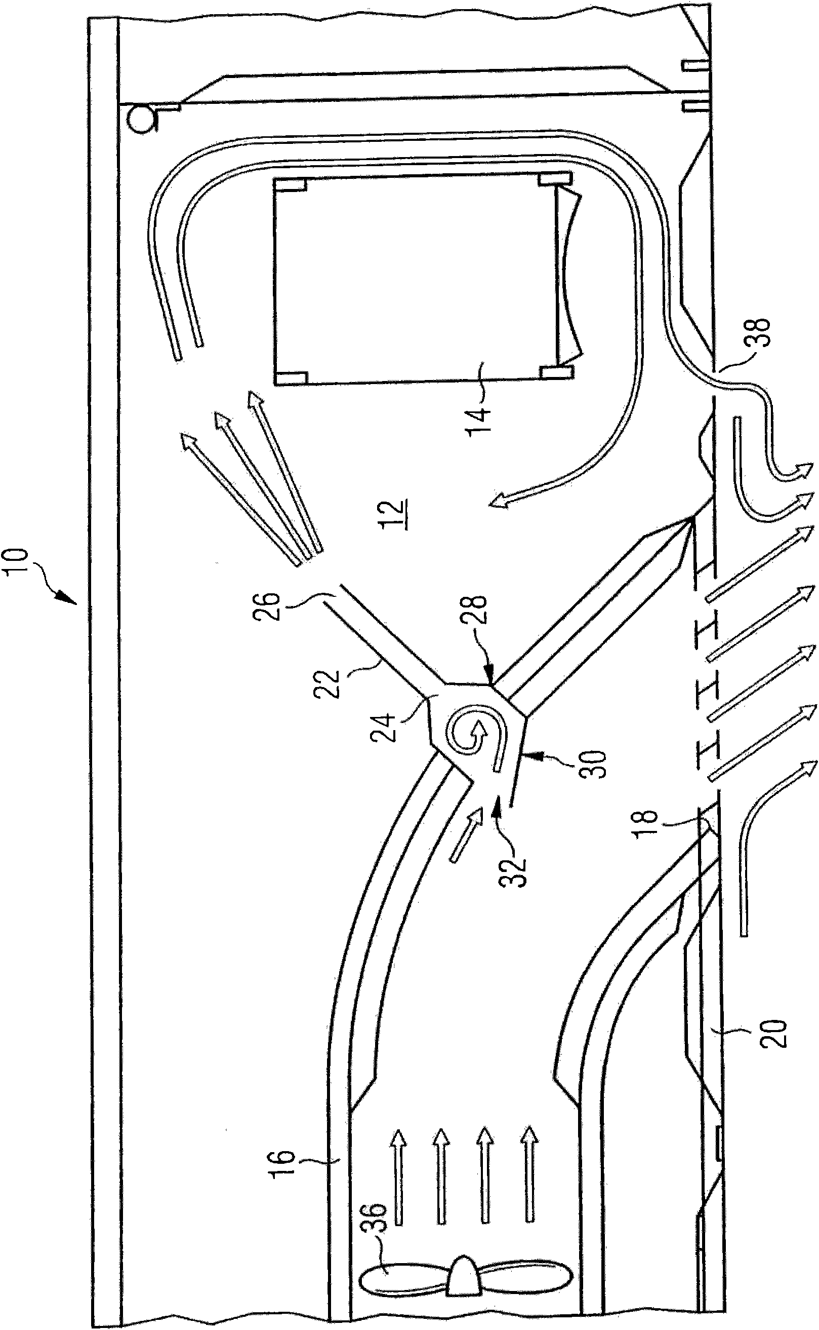
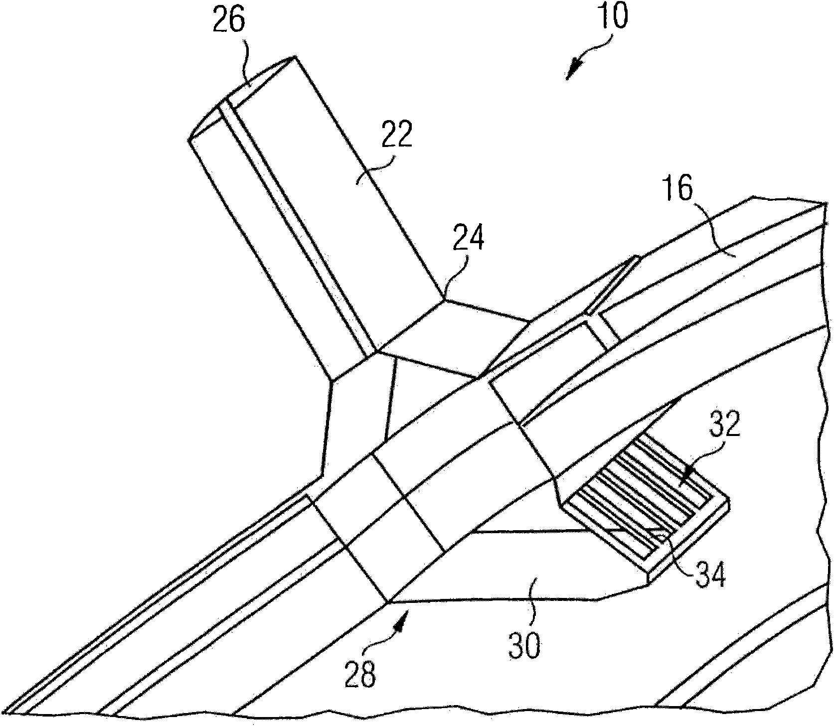
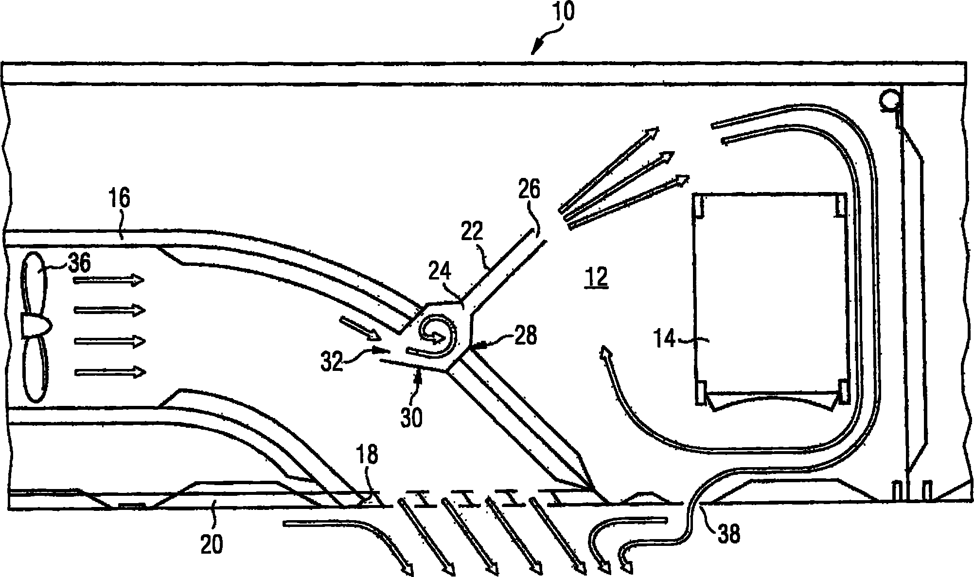
[0022] exist figure 1 A system 10 for ventilating an explosion-hazardous area 12 of a spacecraft is shown in FIG. This explosion-hazardous spacecraft area 12 is adjacent to the spacecraft's fuel tanks (which are not in figure 1 shown in ). For this reason, it is possible for kerosene vapors to seep into zone 12 . A thermal load component 14 in the form of a control unit is arranged in the spacecraft region 12 . In order to prevent the formation of explosive gas mixtures in the area 12 and thereby minimize the risk of fuel explosions, the explosively hazardous spacecraft area 12 must be adequately ventilated. Furthermore, thermally loaded components 14 generate high thermal loads that must be removed from spacecraft region 12 .

[0023] The ventilation system 10 includes a ram air passage 16 having an air inlet that is not in the figure 1is shown in and is designed in the form of a NACA inlet for supplying ambient air to the ram air channel 16 . The air inlets of the ram ...


PUM


Abstract

The invention relates to a system (10) for ventilating an explosive region (12) of an aircraft, comprising a ram air channel (16), which has an air inlet for supplying ambient air into the ram air channel (16), and an air outlet (18). The ram air channel (16) is configured to supply air to a device to be cooled on board of the aircraft. A ventilation line (22) has an air inlet (24) for supplying air flowing from the ram air channel (16) into the ventilation line (22), and an air outlet (26). The ventilation line (22) is configured to supply air to a region (12) of the aircraft to be ventilated. A reservoir (28) is disposed between the ram air channel (16) and the air inlet (24) of the ventilation line (22), said reservoir being configured to convert the dynamic pressure of the air flow directed through the ram air channel (16) at least partially into static pressure.

Description

technical field [0001] The present invention relates to systems and methods for ventilating explosion-hazardous areas of air vehicles, particularly aircraft. Background technique [0002] On a spacecraft, the risk of explosion in the fuel tank can be minimized by filling the empty tank area with an inert gas (eg nitrogen). The inert gas prevents the formation of explosive gas mixtures above the fuel surface. However, inerting by means of inert gases is generally not possible in the region of the spacecraft adjoining the fuel tanks. For this reason, such explosion-hazardous areas are traditionally insulated by means of foils. Furthermore, components which are located in these areas and which may generate sparks or develop high surface temperatures during operation are of explosion-proof design and are equipped with special insulation. Finally, the area of ​​the spacecraft at risk of explosion is intensively ventilated and evacuated, in which an air exchange rate of 3 to 5 ...

Claims


Application Information

Patent Timeline
Patent Type & Authority Applications(China)
IPC IPC(8): B64D37/32B64D13/08B60K15/035
CPCB64D13/08Y02T50/44B64D37/32Y02T50/56B64D2013/0618Y02T50/40Y02T50/50
Inventor 德克·卡斯特尔威尔逊·维·卡萨斯诺列加
Owner AIRBUS OPERATIONS GMBH
Why Eureka
Try Eureka