Method for rapidly determining welding parameter of electron beam

A technology of electron beam welding and parameters, which is applied in the direction of electron beam welding equipment, welding equipment, metal processing equipment, etc., can solve problems such as difficulties, obstacles to the popularization and application of electron beam welding technology, and long cycle time, so as to reduce production costs and shorten product quality. The effect of the lead time

Active Publication Date: 2012-04-18
CHENGDU SIWI HIGH TECH IND GARDEN
View PDF0 Cites 2 Cited by
  • Summary
  • Abstract
  • Description
  • Claims
  • Application Information

AI Technical Summary

Problems solved by technology

However, there are many parameters that affect electron beam welding. In addition to welding height, accelerating voltage, welding beam current, welding speed, and vacuum degree of vacuum chamber, there are also focus positions, scanning waveforms, scanning amplitudes, and scanning frequencies. If you want to determine them one by one, It is very difficult, especially the focus position. On the one hand, the focus parameters are not intuitive and difficult to measure directly; on the other hand, the influence of the focus on the welding quality is a nonlinear relationship; in addition, the metal vapor in the welding process also dynamically affects the focus position
[0003] In industrial production, the physical parameters and geometric parameters of each weldment are different. To determine a set of matching electron beam welding parameters for a certain weldment usually requires a lot of trial welding, testing and repeated correction of each welding parameter, which is not only inefficient but also takes a long time. Moreover, the high cost has caused many companies to stop at this advanced welding technology, which has hindered the further promotion and application of electron beam welding technology to a certain extent.

Method used


Image

  • Method for rapidly determining welding parameter of electron beam
  • Method for rapidly determining welding parameter of electron beam
  • Method for rapidly determining welding parameter of electron beam

Examples


Embodiment Construction

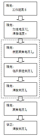
[0024] A method for quickly determining electron beam welding parameters such as figure 1 shown, including the following steps:

[0025] Step 1: Determine the welding working distance S. The electron beam is focused by the electromagnetic coil, and its working distance S determines the size of the focusing current, and the working distance can be freely determined within a certain range. In order to ensure the rapid portability of welding parameters, the working distance of the welding process test piece should be the same as that of the welding workpiece. In addition, the material, state and thickness of the process test piece used to explore the welding parameters before welding the workpiece should be the same as that of the workpiece to be welded.

[0026] The second step: select the acceleration voltage Ua and welding speed ν. The accelerating voltage and welding speed of the electron beam are related to factors such as equipment characteristics, performance, material ...


PUM


Abstract

The invention discloses a method for rapidly determining the welding parameter of an electron beam, comprising the following steps of: determining welding working distance S, and selecting accelerating voltage Ua and welding speed v; determining welding current Ib through critical penetration beam Ic; determining focusing current If through surface focusing current Iof; and modifying the welding beam current Ib. The invention has the advantages that the test method focuses on the determination of the focusing current instead of the determination of welding beam current conventionally on the basis of the laws that the electronic beam welding beam current affects little on the shape of a seam, the shape variation of the seam along with the welding beam current is similar to the whole scaling, the focusing current affect the seam shape more and the fusion width, depth and shape of the seam are dramatically varied, and the like. The invention has obvious advantage in the engineering practical application.

Description

technical field [0001] The invention relates to a welding method, in particular to an electron beam welding method. Background technique [0002] Electron beam is a typical high-energy beam, and its application in the field of welding has obvious characteristics, such as high energy density, fast welding speed, large aspect ratio, small deformation of welded parts, good protection conditions, precise and flexible control, etc. , is widely used in the welding production of refractory materials, active metals, heterogeneous alloys and special structural parts. However, there are many parameters that affect electron beam welding. In addition to welding height, accelerating voltage, welding beam current, welding speed, and vacuum degree of vacuum chamber, there are also focus positions, scanning waveforms, scanning amplitudes, and scanning frequencies. If you want to determine them one by one, It is very difficult, especially the focus position. On the one hand, the focus param...

Claims


Application Information

Patent Timeline
Patent Type & Authority Patents(China)
IPC IPC(8): B23K15/00
Inventor 王远荣刘雁斌魏光明曾雄辉刘志远
Owner CHENGDU SIWI HIGH TECH IND GARDEN
Why Eureka
Try Eureka