Composite material panel array hole detection method based on line laser scanning

A detection method, line laser technology, applied in the field of digital measurement, can solve problems such as difficulty in product acceptance, low confirmation efficiency, affecting production tact and delivery progress, etc., to shorten the delivery cycle, avoid misjudgment, and reliable detection Effect

Active Publication Date: 2021-05-07
CHENGDU AIRCRAFT INDUSTRY GROUP
View PDF29 Cites 8 Cited by
  • Summary
  • Abstract
  • Description
  • Claims
  • Application Information

AI Technical Summary

Problems solved by technology

However, due to the large number of holes, the efficiency of manual inspection one by one is too low. When inspecting holes with a quantity of 10,000, it will seriously affect the production cycle and delivery schedule, and the product acceptance is very difficult.

Method used


Image

  • Composite material panel array hole detection method based on line laser scanning
  • Composite material panel array hole detection method based on line laser scanning
  • Composite material panel array hole detection method based on line laser scanning

Examples


Embodiment 1

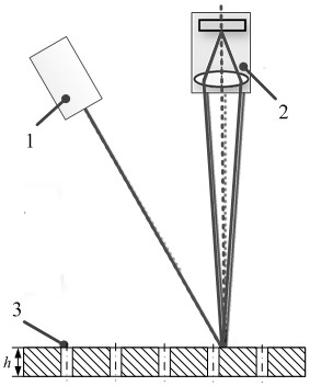
[0034] A method for detecting array holes in composite wall panels based on line laser scanning, such as figure 1 As shown, the laser 1 is used to project a line laser to the surface of the measured object 3, and the laser stripes passing through the surface of the measured object 3 are collected by the industrial camera 2, and then the data of the outer surface of the wall panel and the data of the bottom of the hole are obtained, and the point cloud data obtained from the scan Obtain hole section data row by row in:

[0035] ① If the distance between the point cloud data at the bottom of the hole in the cross-sectional point cloud data and the upper surface of the measured panel is all less than the thickness h of the panel, it is considered that the hole is blocked, for example Figure 5 The first measured hole 6 in the

[0036] ②If the distance between the point cloud data at the bottom of the cross-sectional point cloud data and the upper surface of the measured object 3...

Embodiment 2

[0042] This embodiment is optimized on the basis of Embodiment 1. For the suspected blockage situation, continue to extract the adjacent sections of the current section. The extraction of the section covers the entire aperture range. If it still cannot be judged as a through hole, that is, if it meets the requirements of the section If the distance between the point cloud data of the hole bottom of the point cloud data and the upper surface of the measured wall plate is less than the thickness of the wall plate or the distance between the point cloud data and the upper surface of the measured object 3 is less than the thickness h of the wall plate, then the hole position is considered to block the hole, i.e. no conduction

[0043] Other parts of this embodiment are the same as those of Embodiment 1, so details are not repeated here.

Embodiment 3

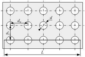
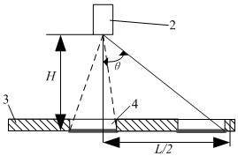
[0045] This embodiment is optimized on the basis of embodiment 1 or 2, as figure 2 , image 3 As shown, an industrial camera 2 is used to measure the measured hole 4, and the laser stripe at the bottom of the measured hole 4 can be photographed, and the length L of the laser stripe is greater than or equal to the size of the covered hole.

[0046] Further, the length L of the laser stripes:

[0047] L≥d u ×(n-1)+d

[0048] And should meet:

[0049]

[0050] Among them, d is the aperture, d u is the horizontal spacing, d v is the vertical spacing, h is the depth, n is the number of holes; H is the distance from the industrial camera 2 to the bottom of the measured hole 4, and θ is the angle between the axis of the optical path and the normal vector of the hole.

[0051] Other parts of this embodiment are the same as those of Embodiment 1 or 2 above, so details are not repeated here.


PUM


Abstract

The invention discloses a composite panel array hole detection method based on line laser scanning, which comprises the following steps of: projecting line laser to the surface of a detected object by adopting a laser device, acquiring laser stripes passing through the surface of the detected object by an industrial camera, further acquiring the outer surface data and hole bottom data of a panel, acquiring hole section data line by line from point cloud data acquired by scanning, judging whether the holes are transparent or not through analysis and processing of the point cloud data, and detecting the through hole rate of the whole panel. The method can be used to quickly and reliably detect the through hole rate of the array holes in aircraft panel parts, improves the detection efficiency and the delivery progress of products, and has good practicability. According to the invention, the line laser scanning technology and the point cloud processing technology are integrated, and rapid detection of the through hole rate of the array holes of the aircraft panel is realized.

Description

technical field [0001] The invention belongs to the technical field of digital measurement, and in particular relates to a method for detecting array holes of composite wall panels based on line laser scanning. Background technique [0002] Noise is an important indicator of the airworthiness of aircraft, especially civil aviation aircraft, and reducing engine noise is one of the keys to aircraft structural design. Aircraft engines reduce and suppress engine noise by using composite material panels and setting a large number of array holes. The diameter of this type of holes is small , The quantity is large (the quantity is in tens of thousands). [0003] Since during the manufacturing process, redundant objects will block the holes, which will lead to the weakening of the noise reduction effect. Therefore, in the acceptance stage, the through-porosity of the holes is used as an important acceptance index, that is, it is necessary to specify the array on the composite pane...

Claims


Application Information

Patent Timeline
Patent Type & Authority Applications(China)
IPC IPC(8): G01N21/84G01B11/14
CPCG01N21/84G01B11/14
Inventor 朱绪胜陈志川申皓陈洪宇
Owner CHENGDU AIRCRAFT INDUSTRY GROUP
Why Eureka
Try Eureka