Method for preparing target structure

A production method and target technology, which are used in manufacturing tools, metal material coating processes, ion implantation plating, etc. The effect of industrial production

Active Publication Date: 2011-01-26
KONFOONG MATERIALS INTERNATIONAL CO LTD
View PDF6 Cites 23 Cited by
  • Summary
  • Abstract
  • Description
  • Claims
  • Application Information

AI Technical Summary

Problems solved by technology

[0006] The problem solved by the present invention is that the bonding strength of the direct welding of chromium or chromi

Method used


Image

  • Method for preparing target structure
  • Method for preparing target structure
  • Method for preparing target structure

Examples


specific Embodiment

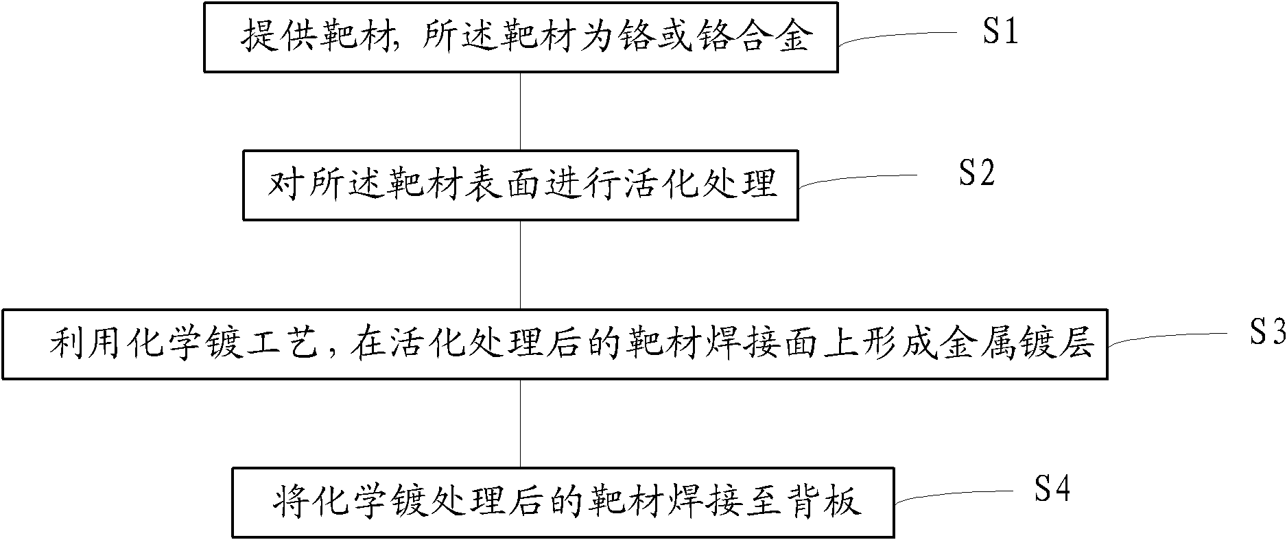
[0075] Take 3N5, 4N5 or 5N chromium targets as examples to illustrate the process steps and results of the present invention:

[0076] (1) Polish each surface of the chromium target material (diameter 310mm, thickness 12mm), first use 160# water-based sandpaper to polish each surface of the target material for 10 minutes (min); then use 400# water-based sandpaper to continue Polish each surface of the target for 8 minutes (min), so that a smooth and bright surface can be obtained;

[0077] (2) Wash each surface of the polished chromium target with pure water or deionized water for 5 minutes (min), and blow dry;

[0078] (3) Perform sandblasting treatment on each surface of the dried chromium target material; use No. 46 white corundum, the air pressure is 0.4MPa, the distance from the nozzle of the sandblasting gun to the surface of the target material is 15cm, and the nozzle sprays The angle between the direction of No. 46 white corundum and the target surface is 60 degrees. After s...


PUM


Abstract

The invention relates to a method for preparing a target structure. The method comprises the following steps of: providing a target, namely chromium or a chromium alloy, and activating the surface of the target; forming a metal plated layer on a solder side of the activated target by a chemical plating process; and soldering the chemically plated target to a back board. By taking the metal plated layer formed on the solder side of a chromium or chromium alloy target by chemical plating as an intermediary, the soldered target and back board are firmly bonded and have higher bonding strength. The invention provides a process for steadily plating a metal layer on the surface of the chromium or chromium alloy target by the chemical plating and realizes industrial production.

Description

Technical field [0001] The present invention relates to the field of semiconductor manufacturing, in particular to a method for manufacturing a target structure. Background technique [0002] Generally, the target assembly is composed of a target that meets the sputtering performance and a back plate that is combined with the target and has a certain strength. The back plate can support the assembly of the target assembly to the sputtering base and has the function of conducting heat. During the sputtering process, the working environment of the target assembly is relatively harsh, for example, the target assembly has a high working temperature, such as 100 degrees Celsius to 300 degrees Celsius; in addition, the target assembly is forced to cool by applying cooling water on one side, and the other One side is at 10 -9 In the high vacuum environment of Pa, a huge pressure difference is formed on the opposite sides of the target assembly; in addition, the target assembly is in a ...

Claims


Application Information

Patent Timeline
IPC IPC(8): C23C14/34B23K1/20
Inventor 姚力军潘杰王学泽袁海军
Owner KONFOONG MATERIALS INTERNATIONAL CO LTD
Why Eureka
Try Eureka