Drive control device of high-speed switch of silicon controlled switched capacitor

A technology of switching capacitors and high-speed switches, which is applied in the directions of reactive power compensation, reactive power adjustment/elimination/compensation, etc., can solve the problem that the implementation idea and the zero-crossing point of the optocoupler detection voltage have no obvious improvement, and the thyristor cannot be accurately detected. Problems such as zero-crossing, inability to work, fast switching conditions, etc., to avoid voltage fluctuations, reduce costs, and improve driving capabilities

Inactive Publication Date: 2013-03-20
北京鼎英能源科技有限公司
View PDF5 Cites 0 Cited by
  • Summary
  • Abstract
  • Description
  • Claims
  • Application Information

AI Technical Summary

Problems solved by technology

On the one hand, this scheme cannot accurately detect the zero-crossing point of the thyristor terminal voltage, and there is a large deviation. It is only suitable for slow thyristors. Generally, the switching interval is required to be greater than a few seconds, and it cannot be applied to fast switching occasions. When the switching speed of the switch is fast, the triggering of the thyristor will be in an unstable state. When the speed reaches a certain level, there will be a serious DC component in the capacitor voltage, the voltage zero-crossing detection of the optocoupler will fail, and the switch will work reactively, which will cause the system disastrous consequences
Another zero-crossing detection circuit built with separate components drives the SCR through optocoupler isolation or electromagnetic isolation. The current zero-crossing detection and isolation drive circuits often use simple capacitors, resistors, and diodes to judge whether the voltage is too high. The zero point, its implementation idea and the zero point of the optocoupler detection voltage have no obvious improvement, and it also cannot work in the fast switching condition of the switch

Method used


Image

  • Drive control device of high-speed switch of silicon controlled switched capacitor

Examples


Embodiment Construction

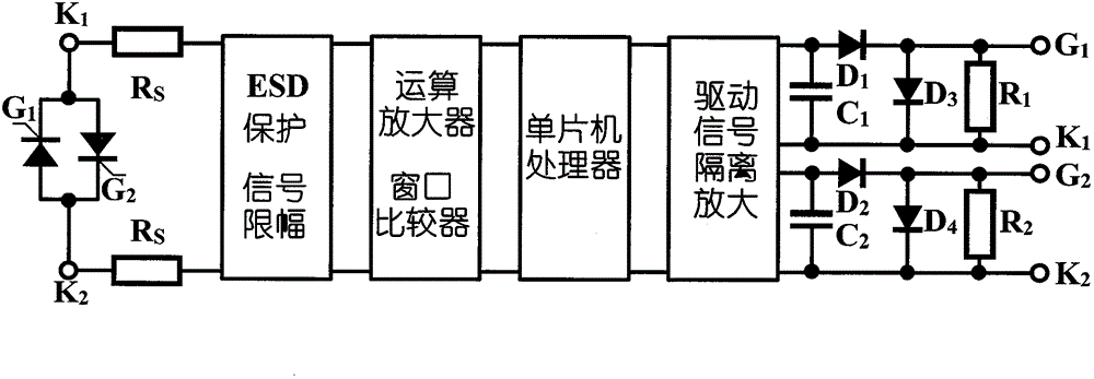
[0017] Such as figure 1 As shown, the drive control device of the thyristor switching capacitor high-speed switch of the present invention consists of a thyristor, an ESD protection and signal limiting module, an operational amplifier and a window comparator module, a single-chip processor, a driving signal isolation amplification module and The driving signal shaping circuit is composed of; the driving control device of the thyristor switching capacitor high-speed switch is connected in parallel with the two ends of the thyristor in the capacitive reactive power compensation device circuit, and two sampling resistors are connected in the control and protection circuit of the thyristor R s , two sampling resistors R s One end of the thyristor and the node K at both ends of the thyristor 1 and K 2 connection, the two sampling resistors R s The other end of the other end is connected with ESD protection and signal limiting module input respectively; The output terminal of ES...


PUM


Abstract

The invention relates to a drive control device of a high-speed switch of a silicon controlled switched capacitor, which comprises controllable silicon, an ESP (Electronic Stability Program) protecting and signal amplitude limiting module, an operational amplifier and a window comparer module, a singlechip processor, a drive signal isolation and amplification module and a drive signal rectifier circuit. According to the invention, a terminal voltage of the controllable silicon is subjected to resistance voltage division, protection against lightning and sampling to obtain a signal waveform of the terminal voltage, a terminal voltage signal which is stabilized by the operational amplifier is processed by the window comparer module to obtain a minimum value point of the voltage and then sent to the singlechip for signal correction and delay to obtain an accurate voltage extreme point, thus a trigger signal of the controllable silicon is generated and sent to the amplification circuit via a signal latch; and the amplified trigger signal is subjected to electromagnetic isolation and then signal correction to trigger the controllable silicon.

Description

technical field [0001] The invention relates to a thyristor switching switch used in a capacitive reactive power compensation device, in particular to a thyristor switch that can accurately capture the moment of the minimum point voltage of the thyristor terminal, safely and reliably trigger and drive the thyristor to work. A drive control device for high-speed switching of silicon controlled switching capacitors. Background technique [0002] There are a large number of capacitive reactive power compensation conditions in the power quality management of the power system to improve the power quality of the system. Among the capacitive reactive power compensation devices currently in use, the switch group switching capacitive reactive power compensation device has the advantages of high cost performance, energy saving, good stability, mature technology, simple system control, good compensation effect, wide application fields, and practical work. It has the advantages of stro...

Claims


Application Information

Patent Timeline
Patent Type & Authority Patents(China)
IPC IPC(8): H02J3/18
CPCY02E40/30
Inventor 李红涛李小红许昌强李志钊
Owner 北京鼎英能源科技有限公司
Why Eureka
Try Eureka