
High resolution time-to-digital converter

A Fractional Delay and Time Shifting Technique Applied in the Field of Time-to-Digital Converters

Active Publication Date: 2014-12-03
QUALCOMM INC
View PDF1 Cites 0 Cited by
  • Summary
  • Abstract
  • Description
  • Claims
  • Application Information

AI Technical Summary

Problems solved by technology

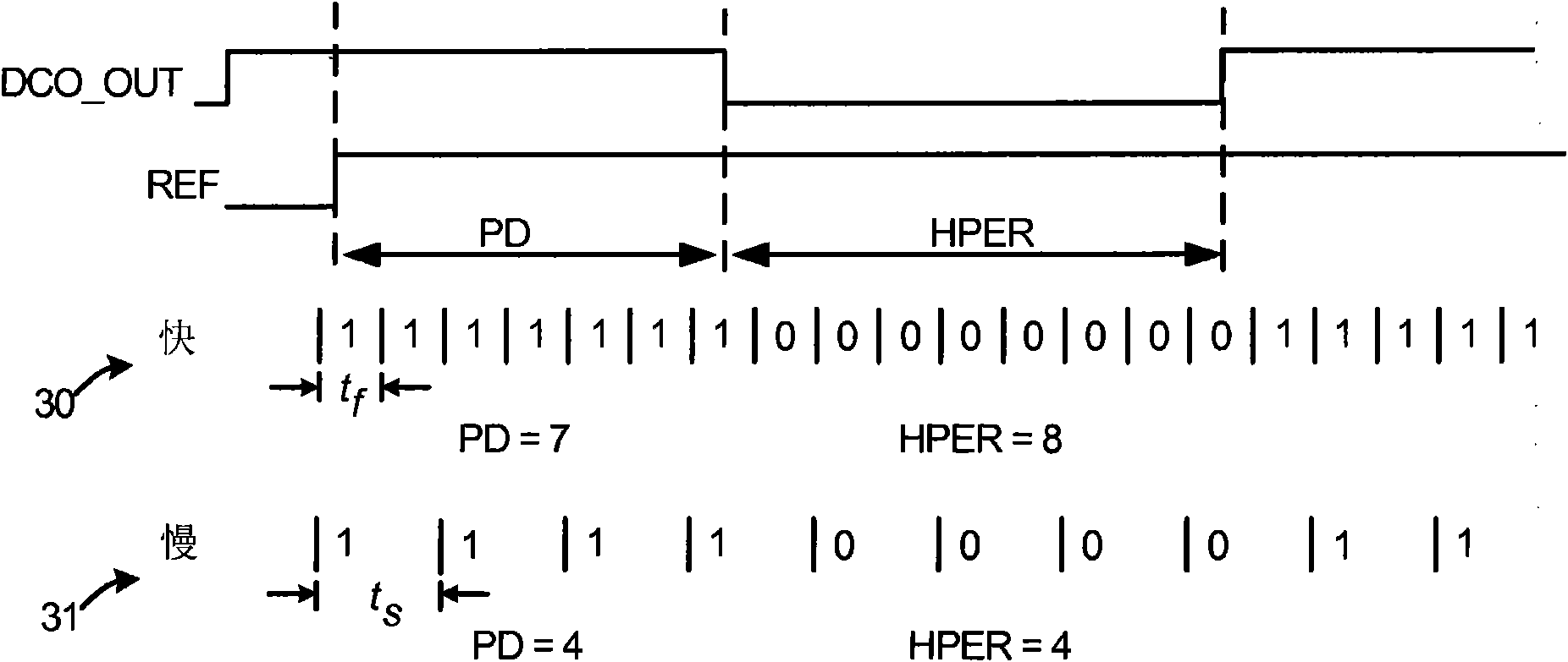
However, if the value HPER is large, relatively few increments of accumulator 33 will be required to cause the overflow condition to occur

Method used


Image

  • High resolution time-to-digital converter
  • High resolution time-to-digital converter
  • High resolution time-to-digital converter

Examples


Embodiment Construction

[0033] Figure 5is a very simplified high level block diagram of one particular type of mobile communication device 100 in accordance with one novel aspect. In this particular example, mobile communication device 100 is a 3G cellular telephone, which uses a Code Division Multiple Access (CDMA) cellular telephone communication protocol. The cellular telephone includes (including several other parts not illustrated) an antenna 102 and two integrated circuits 103 and 104 . The integrated circuit 104 is referred to as a "digital baseband integrated circuit" or a "baseband processor integrated circuit". Integrated circuit 103 is an RF transceiver integrated circuit. The RF transceiver integrated circuit 103 is called a "transceiver" because it includes a transmitter as well as a receiver.

[0034] Figure 6 is a more detailed block diagram of the RF transceiver integrated circuit 103 . The receiver includes a part 105 and a local oscillator (LO) 106 called the "receive chain". ...


PUM


Abstract

A time-to-digital converter (TDC) can have a resolution that is finer than the propagation delay of an inverter. In one example, a fractional-delay element circuit receives a TDC input signal and generates therefrom a second signal that is a time-shifted facsimile of a first signal. The first signal is supplied to a first delay line timestamp circuit (DLTC) and the second signal is supplied to a second DLTC. The first DLTC generates a first timestamp indicative of a time between an edge of a reference input signal to the TDC and an edge of the first signal. The second DLTC generates a second timestamp indicative of a time between the edge of the reference input signal and an edge of the second signal. The first and second timestamps are combined and together constitute a high-resolution overall TDC timestamp that has a finer resolution than either the first or second timestamps.

Description

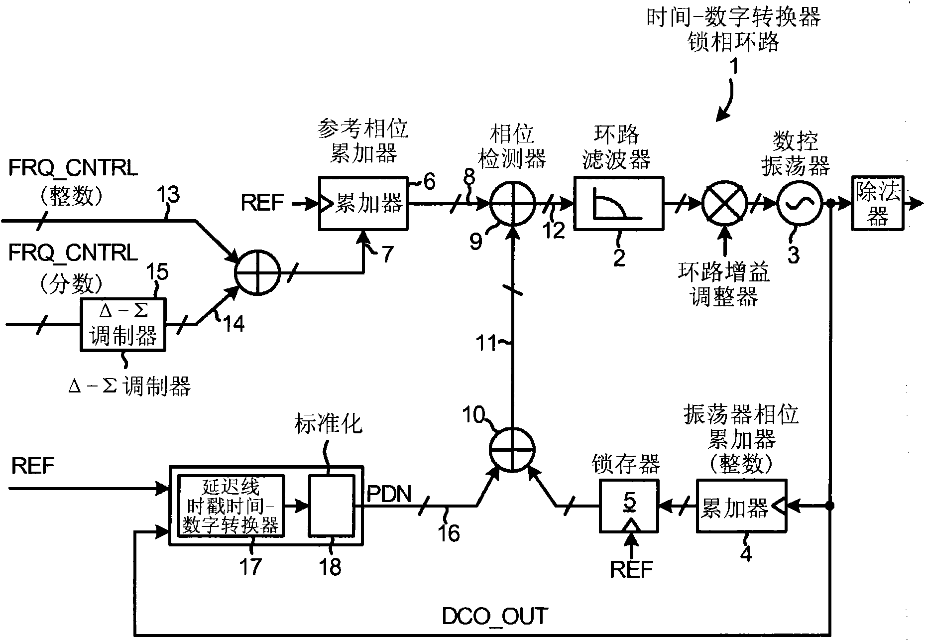
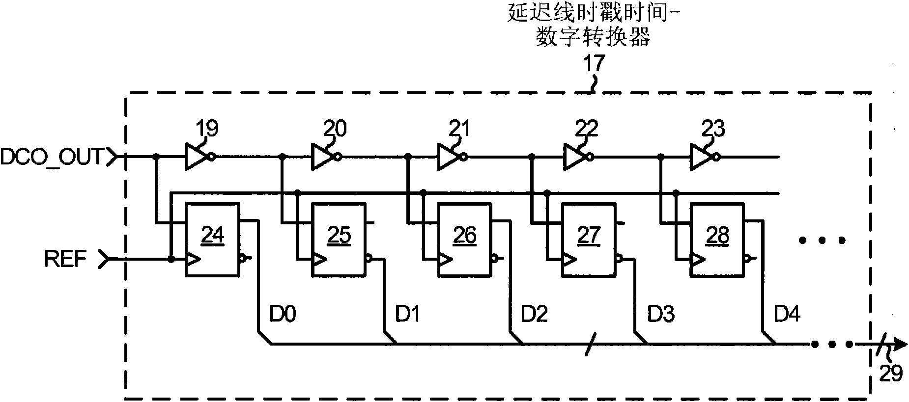
technical field [0001] The disclosed embodiments relate to time-to-digital converters (TDCs). Background technique [0002] A time-to-digital converter (TDC) is a circuit that produces a digital output value (sometimes called a time stamp). The time stamp represents the time elapsed between the edge of the first signal and the edge of the other signal. TDCs have several uses, including in phase locked loops (PLLs). [0003] FIG. 1 (Prior Art) is a highly simplified conceptual block diagram of a TDC PLL 1 . The TDC PLL 1 includes a loop filter 2 that outputs a multi-bit digital tuning word stream. A digitally controlled oscillator (DCO) 3 receives a digital tuning word and outputs a corresponding signal DCO_OUT whose frequency is determined by the digital tuning word. DCO_OUT may, for example, have a frequency in the range of three to four GHz. Accumulator 4 increments every cycle of DCO_OUT, and its value is latched into latch 5 synchronously with reference clock signal...

Claims


Application Information

Patent Timeline
Patent Type & Authority Patents(China)
IPC IPC(8): G06F1/00H03M1/20H03M1/50
CPCG04F10/005
Inventor 孙博杨兹翔
Owner QUALCOMM INC
Learn More