Anti-cavitation centrifugal pump

A centrifugal pump and anti-cavitation technology, applied in the field of centrifugal pumps, can solve the problems of reduced pumping volume, low efficiency, impeller rupture, etc., and achieve the effects of avoiding vibration and noise, ensuring normal operation, and avoiding cavitation

Inactive Publication Date: 2011-02-09
CHONGQING UNIV
View PDF4 Cites 12 Cited by
  • Summary
  • Abstract
  • Description
  • Claims
  • Application Information

AI Technical Summary

Problems solved by technology

Cavitation will cause the centrifugal pump to generate vibration and noise, reduce the performance of the pump, and significantly reduce the flow rate, head and efficiency of the pump; damage the flow-through parts near the impeller outlet and the inlet of the discharge chamber; Perforation, even impeller rupture, causing serious accidents
[0004] In the prior art, there are many methods and structures for preventing cavitation in centrifugal pumps, such as reducing the suction height, adopting double-suction impellers and adopting inducer structures, but all of them need to change the existing structure, and the manufacture and installation are more complicated; the use of backflow Increasing the inlet pressure is also one of the methods used in practice, but after the high-pressure liquid is introduced into the inlet, it mixes with the inlet fluid, resulting in a decrease in the pump's pumping volume and low efficiency

Method used


Image

  • Anti-cavitation centrifugal pump
  • Anti-cavitation centrifugal pump
  • Anti-cavitation centrifugal pump

Examples


Embodiment Construction

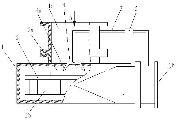
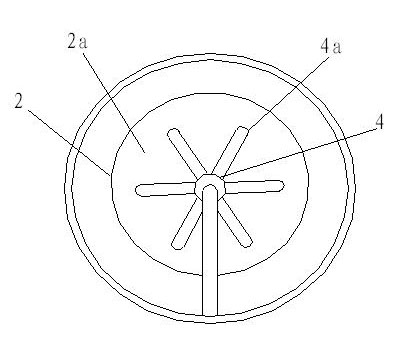
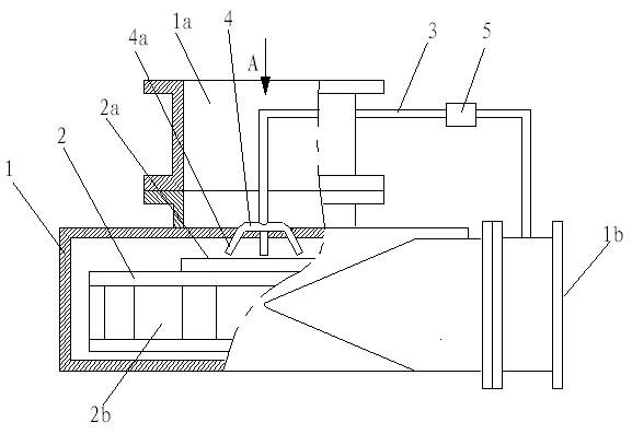
[0015] figure 1 It is a schematic diagram of the structure of the present invention, figure 2 It is a schematic diagram of the nozzle distribution of the injection device, as shown in the figure: the anti-cavitation centrifugal pump of this embodiment includes a pump casing 1 and an impeller 2, the pump casing 1 is provided with a pump inlet 1a and a pump outlet 1b, and the impeller 2 includes an impeller inlet 2a and the impeller outlet 2b, and also includes an ejection device, the ejection device includes an ejection pipe 3 and a nozzle 4a, the liquid inlet of the ejection pipe 3 is connected to the impeller outlet 2b, and the nozzle 4a is facing the impeller inlet 2a low-pressure area It communicates with the liquid outlet of the ejector pipe 3; the impeller inlet 2a low-pressure area is a specific area of ​​the impeller, which refers to the part of the impeller with the lowest pressure when absorbing liquid. After the shape and structure of the impeller are determined, th...


PUM


Abstract

The invention discloses an anti-cavitation centrifugal pump comprising a pump shell, an impeller and an injecting device, wherein the pump shell is provided with a pump inlet and a pump outlet; the impeller comprises an impeller inlet and an impeller outlet; the injecting device comprises an injecting pipe and a spray nozzle, wherein a liquid inlet of the injecting pipe is communicated with an outlet of the impeller; and the spray nozzle just faces to a low-pressure area of the impeller inlet and is communicated with a liquid outlet of the injecting pipe. In the invention, a small amount of high-pressure water is led back to the impeller inlet, and injected the high-pressure water just facing to the low-pressure area of the impeller inlet through the spray nozzle, the pressure of a high-pressure area and the low-pressure area is enhanced by utilizing smaller fluid amount, the pressure intensity of the low-pressure area of the impeller inlet of the centrifugal pump is effectively increased and the centrifugal pump is prevented from generating cavitation, thereby the vibration and the noise and property reduction of the centrifugal pump and the damage of flow passage components, caused by the cavitation, can be avoided; the invention has small utilization amount of high-pressure liquid by pointedly injecting high-pressure and high-flow liquid and rarely influences the liquid striking amount and the efficiency of the centrifugal pump, thereby ensuring that the centrifugal pump can normally operate; and in addition, the invention has the advantage of using and maintaining cost saving.

Description

technical field [0001] The invention relates to a liquid conveying power equipment, in particular to a centrifugal pump. Background technique [0002] Centrifugal pumps are widely used in the fields of chemical industry, energy, domestic or industrial water supply and drainage due to low requirements on fluid properties and installation accuracy, especially in occasions with large flow requirements, and have an irreplaceable role. [0003] The centrifugal pump throws the liquid out through the action of centrifugal force. When the impeller rotates rapidly, the blades make the water rotate quickly, and the rotating water flies away from the impeller under the action of centrifugal force. After the water in the pump is thrown out, the impeller The central part of the pump forms a vacuum area, and the liquid is pressed into the water inlet pipe through the pipe network under the action of atmospheric pressure (or water pressure), forming a cycle to achieve the purpose of contin...

Claims


Application Information

Patent Timeline
IPC IPC(8): F04D29/66
Inventor 何川龙天渝徐浩李少华何丹时雯
Owner CHONGQING UNIV
Why Eureka
Try Eureka