Auxiliary electrode structure for organic light emitting diode (OLED) illuminating panel

An auxiliary electrode and panel technology, applied in the direction of circuits, electrical components, electric solid devices, etc., can solve the problems of improving the brightness uniformity of the panel, reducing the light transmission area of ​​the panel, reducing the aperture ratio of the panel, etc., so as to improve the uniformity of brightness performance, extended device life, and slowed down material aging

Inactive Publication Date: 2011-02-09
SICHUAN CCO DISPLAY TECH
View PDF5 Cites 15 Cited by
  • Summary
  • Abstract
  • Description
  • Claims
  • Application Information

AI Technical Summary

Problems solved by technology

In the prior art, the added auxiliary electrode has a network structure connected to each other on the transparent anode layer, its lower part communicates with the transparent anode, and its upper part is located in the light-emitting layer, so the thickness of the entire auxiliary electrode along the thickness direction of the lighting panel is relatively small , the effect of improving the brightness uniformity of the panel is greatly limited; in addition, because the auxiliary electrode is opaque, light cannot pass through, so after the auxiliary electrode is added, the light emitted by the light-emitting layer above the auxiliary electrode cannot enter the transparent anode layer, thereby reducing the The light-transmitting area of ​​the panel reduces the aperture ratio of the panel. In this way, a higher driving voltage is required to obtain the same brightness, and the power consumption increases accordingly, heat generation increases, and the service life decreases.

Method used


Image

  • Auxiliary electrode structure for organic light emitting diode (OLED) illuminating panel
  • Auxiliary electrode structure for organic light emitting diode (OLED) illuminating panel
  • Auxiliary electrode structure for organic light emitting diode (OLED) illuminating panel

Examples


Embodiment Construction

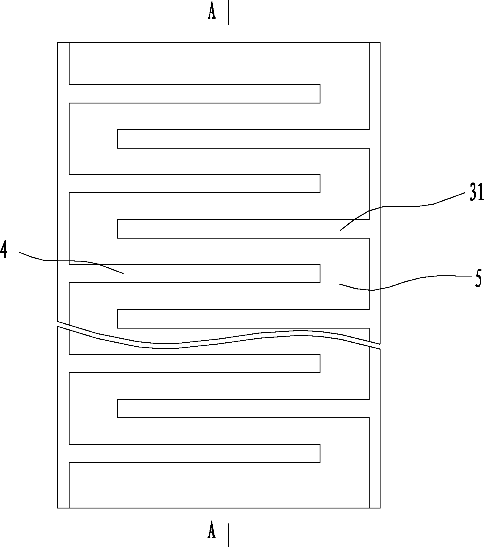
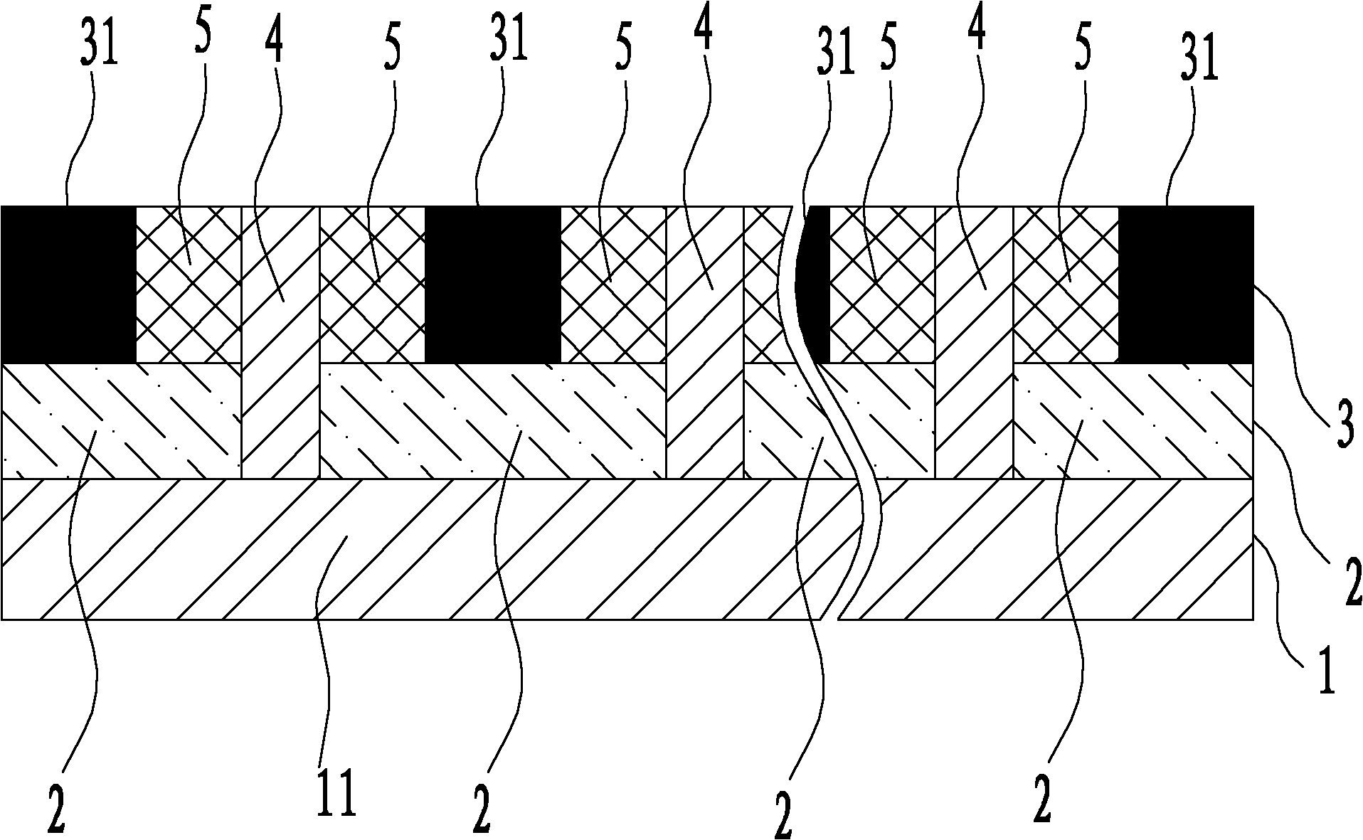
[0011] Such as figure 1 , figure 2 Shown is an auxiliary electrode structure for OLED lighting panels with small impedance, small current voltage drop, and high brightness uniformity provided by the present invention. The auxiliary electrode structure includes an anode layer 1 at the bottom, a cathode layer 3 at the top, a luminescent layer 2 between the anode layer 1 and the cathode layer 3, and an auxiliary electrode 4. The anode layer 1 is made of transparent The anode 11 is formed, the cathode layer is composed of a metal cathode 31, and the auxiliary electrodes 4 themselves communicate with each other and communicate with the transparent anode 11. It is characterized in that: the auxiliary electrode 4 passes through the light emitting layer 2 and extend into the cathode layer 3 ; between the auxiliary electrode 4 and the metal cathode 31 there is an insulating spacer column 5 separating the auxiliary electrode 4 from the metal cathode 31 . Like this, by thickening the ...


PUM


Abstract

The invention relates to an auxiliary electrode structure for an organic light emitting diode (OLED) illuminating panel and provides an auxiliary electrode structure with low impedance, small current pressure reduction and high uniformity for an OLED illuminating panel, which belongs to the technical field of the manufacturing of illuminating panels. The auxiliary electrode structure for the OLED illuminating panel comprises an anode layer, a cathode layer, a luminous layer and an auxiliary electrode, wherein the anode layer is positioned on a lower part of the auxiliary electrode structure; the cathode layer is positioned on an upper part of the auxiliary electrode structure; the luminous layer and the auxiliary electrode are positioned between the anode layer and the cathode layer; the anode layer consists of transparent anodes; the cathode layer consists of metal cathodes; the auxiliary electrodes are communicated with one another and communicated with the transparent anodes; each auxiliary electrode passes through the luminous layer and extends into the cathode layer; and an insulating isolation post for isolating the auxiliary electrode from the metal cathode is arranged between the auxiliary electrode and the metal cathode.

Description

technical field [0001] The invention relates to an auxiliary electrode structure for an OLED lighting panel, belonging to the technical field of lighting panel manufacturing. Background technique [0002] The auxiliary electrode structure of the existing OLED lighting panel is composed of a transparent anode layer, a light emitting layer and a metal cathode layer. / □, the current voltage drop is serious, resulting in obvious uneven brightness of the lighting panel. In order to improve the unevenness of the brightness of the lighting panel, many schemes have been proposed. Basically, auxiliary electrodes connected to the transparent anode and connected to each other are added on the transparent anode layer. Small, about 1Ω / □, the current voltage drop is reduced. When the power is turned on, the impedance and current voltage drop of the transparent anode of the panel are reduced, and the brightness uniformity is improved to a certain extent. In the prior art, the added auxil...

Claims


Application Information

Patent Timeline
Patent Type & Authority Applications(China)
IPC IPC(8): G09G3/32H01L27/32G09G3/3208
Inventor 周刚
Owner SICHUAN CCO DISPLAY TECH
Why Eureka
Try Eureka