
Method for removing magnetic particles from fischer-tropsch synthetic crude oil and method for manufacturing fischer-tropsch synthetic crude oil

A technology of magnetic particles and a manufacturing method, which is applied in the preparation of liquid hydrocarbon mixture, refining by filtration, refining by electric/magnetic, etc., can solve the problems of high washing frequency of fillers, shortened washing interval, and reduced capture efficiency, etc. To extend the washing interval, improve efficiency, enhance the effect of magnetic

Inactive Publication Date: 2011-02-09
JAPAN OIL GAS & METALS NAT CORP +5
View PDF15 Cites 1 Cited by
  • Summary
  • Abstract
  • Description
  • Claims
  • Application Information

AI Technical Summary

Problems solved by technology

[0007] However, since the particles in FT synthetic crude oil are fine and the amount is large, the washing frequency of the filler is high
That is, if it is introduced into the rear stage of the FT synthesis reactor along the magnetic separator, the FT slurry with a high catalyst concentration is directly processed by the magnetic separator, so the capture efficiency is likely to decrease
Therefore, it is not efficient to have to shorten the washing interval

Method used


Image

  • Method for removing magnetic particles from fischer-tropsch synthetic crude oil and method for manufacturing fischer-tropsch synthetic crude oil
  • Method for removing magnetic particles from fischer-tropsch synthetic crude oil and method for manufacturing fischer-tropsch synthetic crude oil
  • Method for removing magnetic particles from fischer-tropsch synthetic crude oil and method for manufacturing fischer-tropsch synthetic crude oil

Examples


no. 1 approach

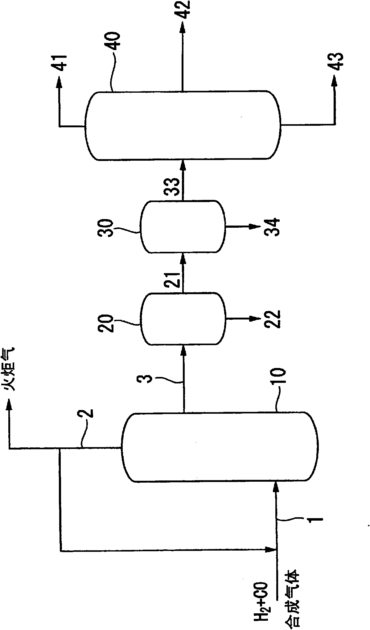
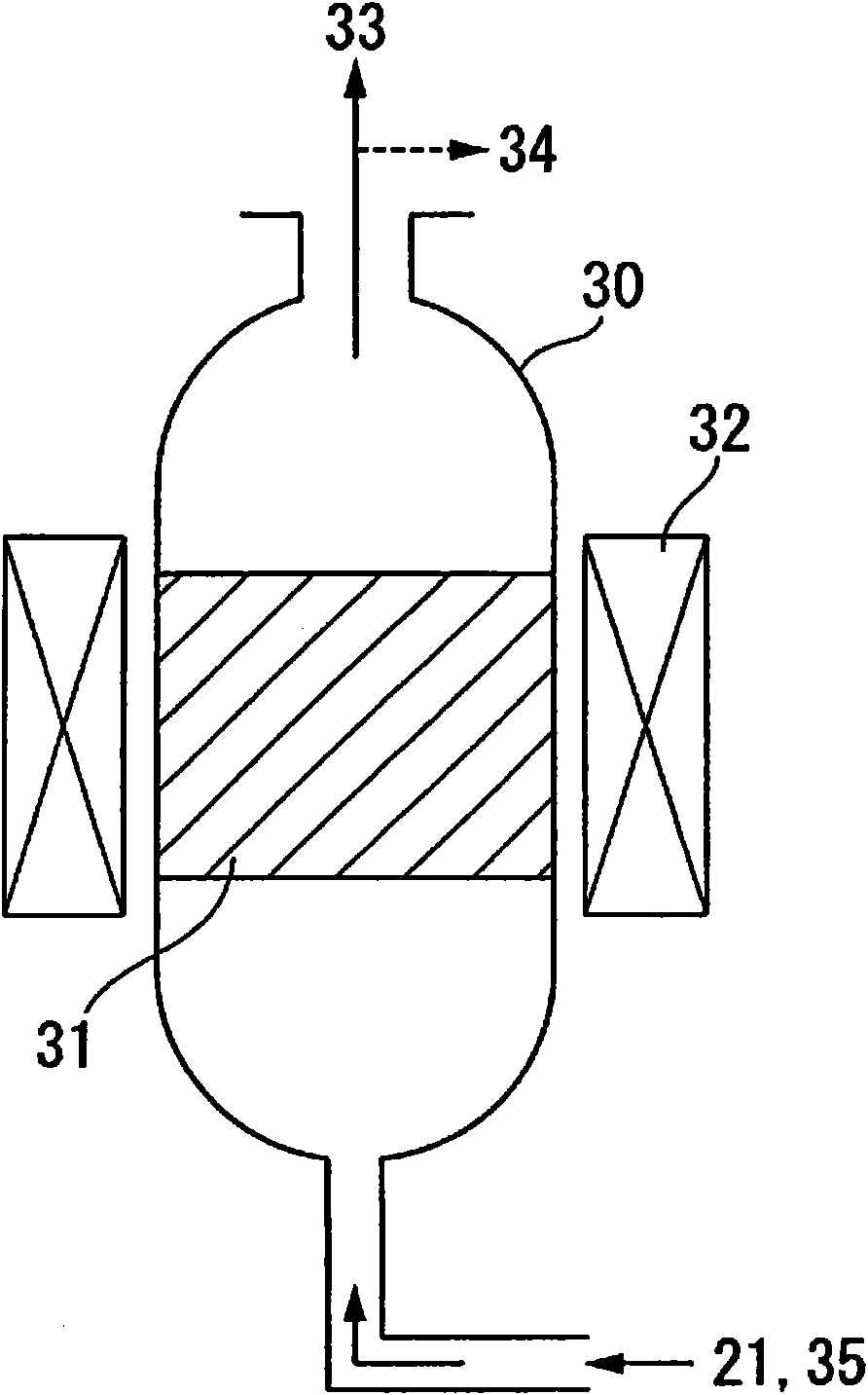
[0030] refer to figure 1 and figure 2 A first embodiment of the present invention will be described.

[0031] like figure 1 As shown, synthesis gas containing carbon monoxide gas and hydrogen gas is supplied to the FT synthesis reactor 10 through a line 1 serving as a synthesis gas supply line, and liquid hydrocarbons are produced by the FT synthesis reaction in the FT synthesis reactor 10 . Synthesis gas can be obtained, for example, by suitable reforming of hydrocarbons or the like. Methane, natural gas, LNG (liquefied natural gas), etc. are mentioned as a representative hydrocarbon. As the reforming method, partial oxidation reforming (POX) using oxygen, autothermal reforming (ATR) which is a combination of partial oxidation reforming and steam reforming, carbon dioxide gas reforming, etc. can also be used. .

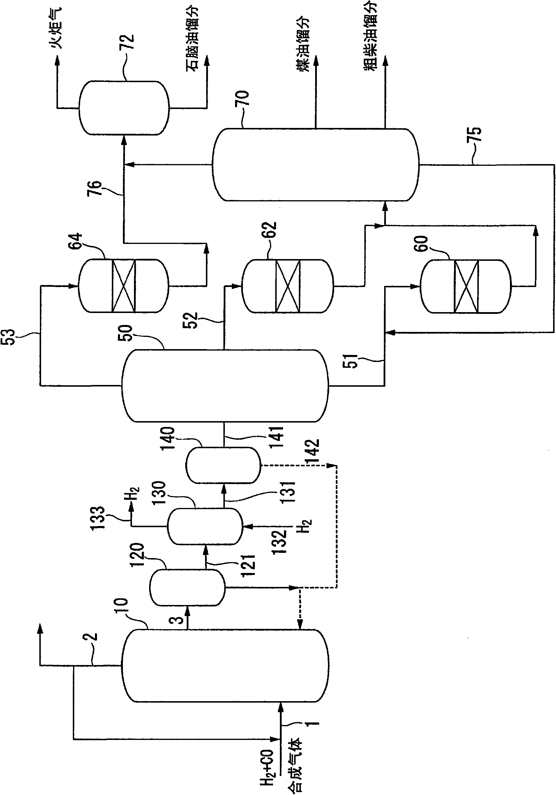
[0032] Refer below figure 1 The FT synthesis process will be described.

[0033] The FT synthesis reaction system has an FT synthesis reactor 10 . The react...

Embodiment 1

[0064] Synthesis gas containing carbon monoxide and hydrogen as main components obtained by reforming natural gas is introduced into a bubble column type hydrocarbon synthesis reactor (FT synthesis reactor) 10 through a line 1, and FT catalyst particles (average particle diameter: 100 μm, Liquid hydrocarbons were synthesized by reacting in a slurry in which 30% by weight of active metal (cobalt) was suspended.

[0065] The liquid hydrocarbons synthesized in the FT synthesis reactor 10 are taken out from the reactor 10 through the line 3 as a slurry containing FT catalyst particles. The withdrawn slurry was passed through the first solid-liquid separator (gravity sedimentation separator / natural sedimentation method) 20 disposed at the rear stage of the FT synthesis reactor 10 to remove catalyst particles.

[0066] Next, the synthetic crude oil (liquid A) containing catalyst particles not separated by the first solid-liquid separator 20 is guided to an electromagnet-type high-gr...

Embodiment 2

[0072] The settling time of the gravity settling separator 20 in the first solid-liquid separation step was adjusted so that the residual particle concentration (ppm by mass) at the inlet of the magnetic separator became the concentration described in Table 1. In addition, as shown in Table 1, the treatment conditions of the high-gradient magnetic separator in the second solid-liquid separation step were changed. Except for this, the same processing as in Example 1 was performed.


PUM

PropertyMeasurementUnit
diameteraaaaaaaaaa
heightaaaaaaaaaa
diameteraaaaaaaaaa

Abstract

Disclosed is a method for removing magnetic particles from Fischer-Tropsch synthetic crude oil, comprising: a solid-liquid separation process in which solid components are separated from synthetic crude oil formed by a Fischer-Tropsch synthesis reaction; and a magnetic separation process in which magnetic particles present in the synthetic crude oil that has undergone the solid-liquid separation process are trapped, and the magnetic particles are separated from the synthetic crude oil. The magnetic separation process is conducted using a high gradient magnetic separator having a cleaning solution introduction line that introduces a cleaning solution to intermittently wash the trapped magnetic particles, and a cleaning solution discharging line that discharges the cleaning solution after the solution is used to wash the magnetic particles.

Description

technical field [0001] The present invention relates to the separation of magnetic particles contained in FT synthetic crude oil obtained by the Fischer-Tropsch synthesis method (hereinafter referred to as "FT synthesis method") using carbon monoxide and hydrogen as raw materials from slurry by using a magnetic separator Methods. [0002] This application claims priority based on Japanese Patent Application No. 2008-65774 and Japanese Patent Application No. 2008-65769 filed on March 14, 2008, the entire contents of which are incorporated herein. Background technique [0003] In recent years, from the viewpoint of reducing the environmental load, there has been a demand for an environmentally friendly green liquid fuel with a low content of sulfur components and aromatic hydrocarbons. Therefore, in the petroleum industry, Fischer-Tropsch synthesis using carbon monoxide and hydrogen as raw materials has been studied as a method for producing green fuel. According to this FT ...

Claims


Application Information

Patent Timeline
Patent Type & Authority Applications(China)
IPC IPC(8): B01J38/00C10G2/00B01J38/10
CPCB01J38/56C10G2/342B01J23/94B01J37/342C10G2/32C10G31/08B01J35/0033B01J35/023B01J23/75B01J38/72C10G31/09C10G32/02
Inventor 田坂和彦
Owner JAPAN OIL GAS & METALS NAT CORP
Learn More