

Blood flow simulation device
A blood flow, simulation device technology, applied in biochemical cleaning devices, enzymology/microbiology devices, animal cells, etc., can solve problems such as the influence of blood flow characteristics
- Summary
- Abstract
- Description
- Claims
- Application Information
AI Technical Summary
Problems solved by technology
Method used
Image

Examples
example 1
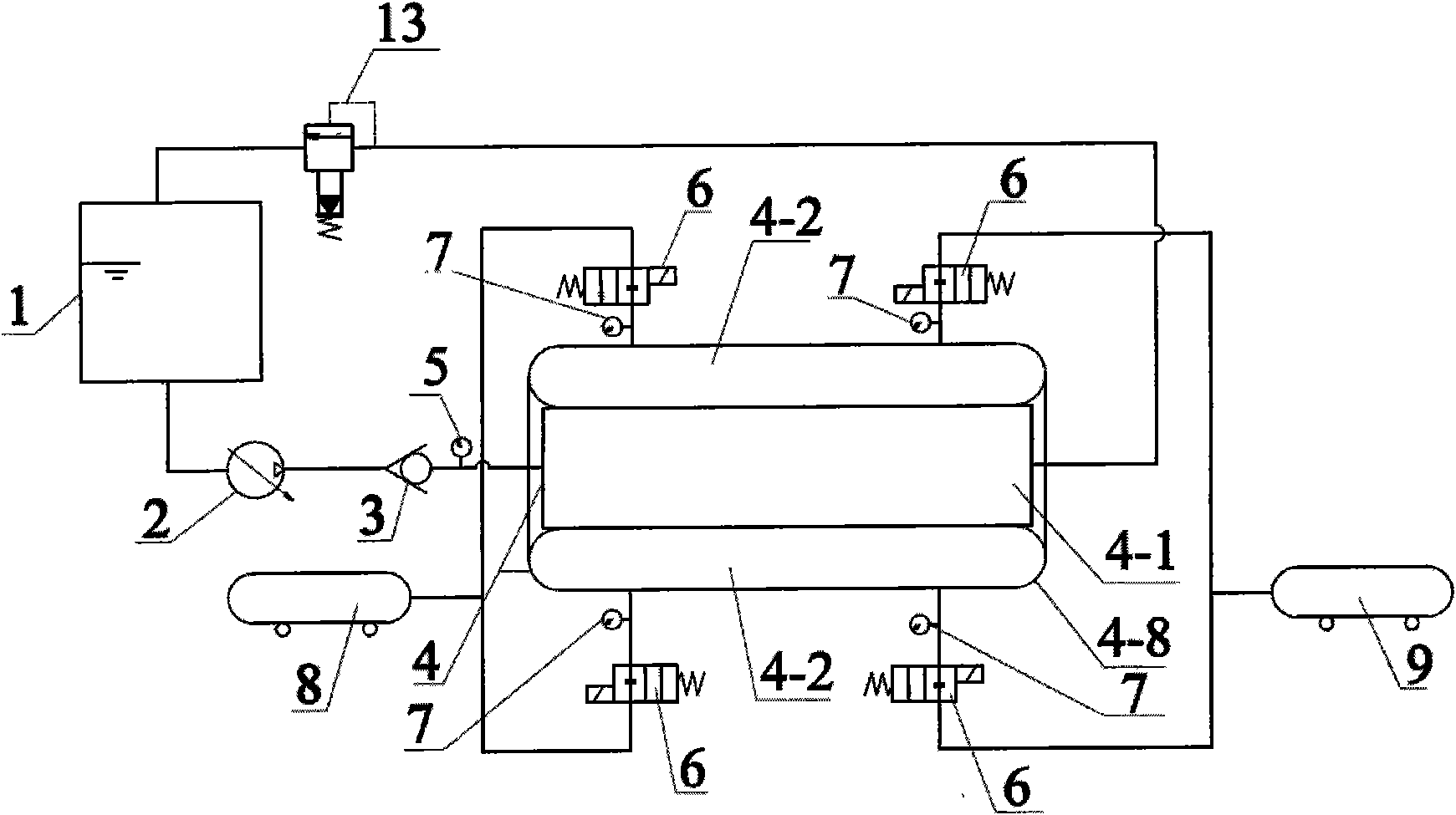
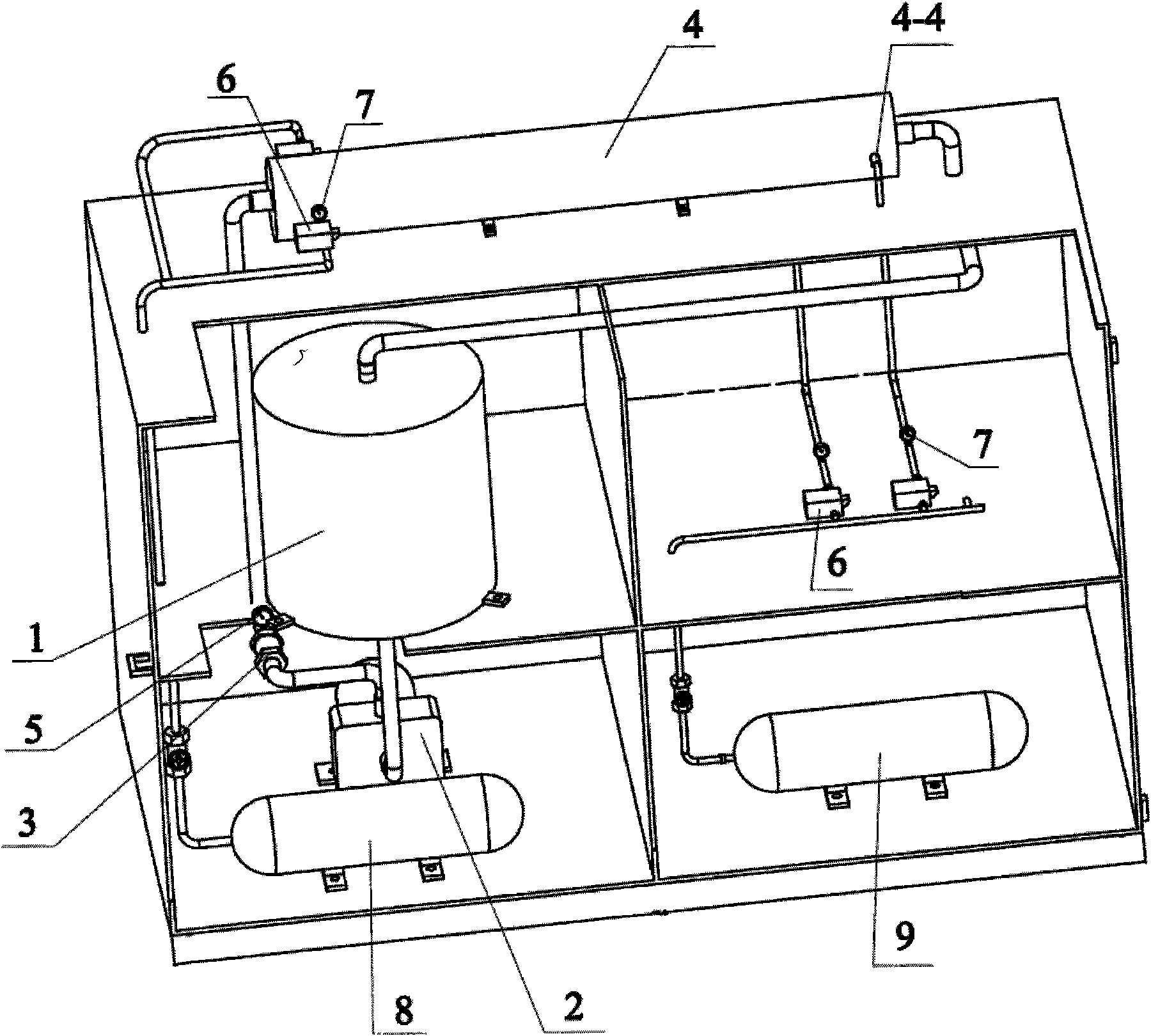
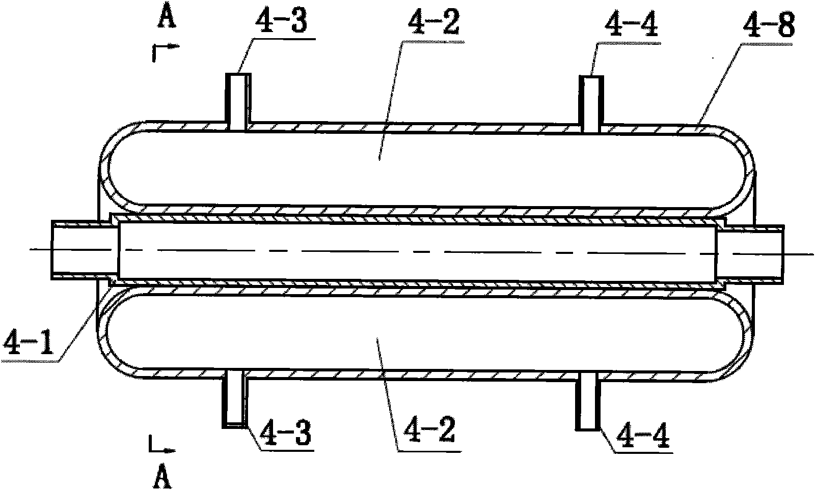
[0024] see Figure 1 ~ Figure 3 , the blood flow simulation device in this embodiment is a closed circulating liquid flow system composed of a liquid storage tank 1, a peristaltic pump 2, a one-way valve 3, a simulation chamber 4 and a back pressure valve 13 which are sequentially connected end to end through pipelines, wherein, A pressure gauge 5 is provided between the one-way valve 3 and the simulation chamber 4 . The simulated cavity 4 is composed of a simulated blood vessel 4-1 and an annular interlayer balloon 4-8 tightly sleeved outside the simulated blood vessel 4-1, wherein, the two sides of the outer wall of the inner layer of the annular interlayer balloon 4-8 are respectively directed toward the outer wall of the outer layer. A longitudinal partition 4-5 is extended on the inner wall, and the annular space in the annular interlayer airbag is divided into upper and lower two air chambers 4-2, and each air chamber 4-2 is provided with an air inlet 4-3 and an air outl...
example 2
[0026] see Figure 5 The difference between this embodiment and Example 1 is that the simulated cavity is composed of a simulated blood vessel 4-1 and two annular sandwich balloons 4-8 tightly sleeved outside the simulated blood vessel 4-1, wherein the simulated blood vessel 4-1 is made of elastic fiber material Made, annular sandwich airbag 4-8 is made of polypropylene film (PP) material.
[0027] In this example, the implementation method other than the above is the same as Example 1.
example 3
[0029] see Figure 6 , the difference between the present embodiment and example 1 and example 2 is that the simulated blood vessel 4-1 is made of rubber material, and the annular sandwich airbag 4-8 is made of polyvinyl chloride film (PVC) material; the annular sandwich airbag 4- 8. Two layers of transverse partitions 4-6 extend from the outer wall of the inner layer to the inner wall of the outer layer, and divide the air chamber 4-2 into three sections in the axial direction.
[0030] In this example, the implementation method other than the above is the same as Example 1.
PUM
 Abstract
Description
Claims
Application Information